Download
1 / 33
330 likes | 475 Views
CLIC and Other Options for Multi-TeV Lepton Physics. Tor Raubenheimer Accelerator Research Division Head, SLAC P5 Meeting Fermilab February 1 st , 2008. Introduction. Outline CLIC concept (X-band Two-Beam Accelerator) Technology status Outstanding issues LC roadmap and other options

E N D
CLIC and Other Optionsfor Multi-TeV Lepton Physics Tor Raubenheimer Accelerator Research Division Head, SLAC P5 Meeting Fermilab February 1st, 2008
Introduction • Outline • CLIC concept (X-band Two-Beam Accelerator) • Technology status • Outstanding issues • LC roadmap and other options • Assumptions • Believe that the motivation for TeV-scale LC remains the same but timescale is slower, motivating a broad look at LC technology • Caveats • Evaluation of outstanding issues for CLIC design is my opinion • Suggestions for ‘other options’ is also my opinion • These views are not endorsed by SLAC, the GDE, or … • I (and SLAC) are committed to developing the ILC as the near-term solution for a 500 GeV LC
What is CLIC? • CLIC = Compact LInear Collider • Developed by CERN originally as a 30 GHz and 150 MV/m that is based on a two-beam accelerator concept • Two-beam concept is an efficient way to transform rf frequency from long-pulse low-frequency short-pulse high-frequency and thereby drive high gradients • Concept is elegant but still waiting for demonstrations and detailed costs illustrating the benefits • Developed parameters from 500 GeV 3TeV • Recently changed parameters to 12 GHz and 100 MV/m to reduce cost and better utilize GLC/NLC R&D • Development program to demonstrate ~100 MV/m by 2010 • CTF3 test facility should demonstrate TBA concept on a similar timescale
Two-Beam Accelerator Concept(from R. Corsini; 2006 parameters)
CLIC RF Module ~ 2 meters Main Beam ~1 A Accelerating structure, +100 MV/m, 64 MW, 229 mm Drive Beam 100 A rf distribution Power Extraction Structures: -6.5 MV/m, 136 MW, 210 mm
CLIC Schematic (2007 Parameters for 3 TeV) Similar number of klystronsas 500 GeV ILC Drive beam complex efficientlygenerates high power beam Main linacs have deccelerator struct-ures adjacent to accelerator structures in single tunnel – all LLRF and complicated electronics are elsewhere Injector systems similarto other LC concepts
Possible CLIC Siting Option CERN site Prevessin Detectors and Interaction Point IP under CERN Prevessin site Phase 1: 1 TEV extension 19.5 km Phase 2: 3 TeV extension 48.5 km
Cost for TBA versus Conventional LC • Major study needed as part of CLIC CDR but characteristics can be understood. The TBA has a large central infrastructure that generates drive beam • Cost per GeV of TBA is likely cheaper than that of a conventional klystron-based linear collider • Initial cost of the TBA is higher than that of a klystron-based collider • Location of cross-over and slopes is unknown for present technologies From 1998 comparisonof 1996 NLC versus X-band TBA costs by G. Loew Cms GeV
GLC/NLC >50 MV/m Operation Single Structures Eight Structure Average Breakdown Rate at 60 Hz (#/hr) with 400 ns Pulses NLC/GLC Rate Limit Breakdown performance continued to improve with time BDR ~ exp(- t / 400 hrs)over the 2000 hrs operation Unloaded Gradient (MV/m)
100 MV/m Structure testing at NLCTA(Structures from GLC/NLC program in early 2000’s) • Run slotted, a/l = 0.18, 75 cm NLC structure (H75vg4S18) with 150 ns pulses - at 102 MV/m, breakdown rate = 6 10-6 • Run early NLC, non-slotted, 53 cm, smaller aperture (a/l = 0.13) structure (T53vg3MC) at short pulses – unloaded gradient at a 10-6 breakdown rate with 100 ns pulses is 105 MV/m and more recently it achieved similar gradient with 200ns ramped pulse. • Building CERN-designed structures for future tests at SLAC and KEK
Single Cell Accelerator Structure Testing(Understand Fundamental Breakdown Limits) Goals • Study rf breakdown in practical accelerating structures: dependence on circuit parameters, materials, cell shapes and surface processing techniques Difficulties • Full scale structures are complex and expensive Solution • Single cell Traveling wave (TW) and single cell standing wave (SW) structures with properties close to that of full scale structures This program, now, has a strong participation from both KEK and CERN. Time of flat pulse after filling time Variety of Single Cell Accelerator Structures Manufactured at KEK SW accelerator structure test with a/l~0.21. In this type of structures loaded and unloaded gradients are the same
CTF3 – CLIC Test Facility • Large-scale LC test facility to demonstrate TBA concept 2004 2005 Thermionic gun Linac DL CR 2007 30 GHz production (PETS line) and test stand TL2 2007-2008 CLEX2007-2009 building in 2006/7 Photo injector / laser tests from 2008 Beam up to here Major milestones in 2007: Combiner Ring (CR) installed CLEX building finished, equipment installation started 150 MeV 30 A - 140 ns
RF Unit Demonstrations(What is necessary before construction?) • The ‘RF Unit’ is the acceleration element that is replicated through the main linacs • Usually thought of as the minimal element that needs demonstration before construction -- CLIC is different • In GLC/NLC: two 75-MW klystrons, SLED-II rf pulse compression system and 4.8 meters of accelerator structure operating at 50 MV/m loaded ~250 MeV per rf unit • Pieces demonstrated in 2004; System demo canceled • In ILC: a modulator and klystron, an rf distribution system, and 3 cryomodules with 26 1-meter rf cavities operating at 31.5 MV/m ~1 GeV per rf unit • Pieces to be demonstrated in 2010; System demo in ~2012 • In CLIC: a 2.5 GeV 100 Amp drive beam is fed into ~600 meters of decellerator structures that accelerate the primary by ~60 GeV • Pieces demonstrated in ~2012 in CTF3 but no RF Unit demo
Outstanding Issues for CLIC • Program to develop high-gradient accelerator structures by 2010 • May not achieve 100 MV/m at desired breakdown rate but, given present results, will probably be close • Systematic cost estimate needed • Working with GDE to develop costs using same methodology as applied to ILC – aiming for 2010-timescale • Tighter alignment and jitter tolerances • Aiming to demonstrate stabilization techniques by 2010 • Program to demonstrated TBA-concept in CTF3 by 2012 and accelerate beams to ~1 GeV • Concept demonstrated but drive beam parameters quite different from CLIC and will not demonstrate an ‘RF Unit’ • Not clear what is necessary to launch construction and the collaboration is discussing options
Understanding the Gradient Choice • Cost optimum is a balance between costs proportional to length, i.e. tunnel & structures and costs proportional to the rf power sources G = A sqrt(P * Rs)P = rf power / meter Rs = shunt imp. / m • Have to reduce rf powercost per MW by 2x or double shunt imped. to increase G by 40% GLC/NLC X-band At low gradient, cost increases due to larger length costs Relative TPC At high gradient, cost increases due to higherrf power costs Unloaded Gradient (MV/m)
CLIC Gradient Optimization • CERN developed a detailed cost estimate using the TESLA estimate and the US Technical Options Study (2003) costing • Not entirely clear whatis included and whatdrives the frequencyscaling but the basicform makes sense • Believe that there isan assumption thatabove 10 GHz, thegradient is independentof frequency • Main point: very highgradients don’t make cost sense Cost Previous New Optimum
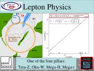
Approaches to a Linear Collider(Four Options) • Superconducting rf (1.3 GHz) • Strong international support through ILC collaboration • Gradients of 30 MV/m in cavities yielding 20 MV/m average • Technology well advanced (1 GeV test facilities under construction at Fermilab and KEK 2011 or 2012) • Can be stretched to ~1 TeV energy • Normal conducting rf (11 ~ 12 GHz) • Strong international support through CLIC collaboration • CLIC recently adopted 12 GHz down from 30 GHz • Gradients of 100 MV/m yielding 80 MV/m average • Technology fairly well advanced (test facility at SLAC demonstrated 300 MeV at 50 MV/m in 2004 and CTF3 at CERN aiming for 1 GeV at 100 MV/m in 2012 - 2014) • Certainly reach 1 TeV and maybe multi-TeV energies
Approaches to a Linear Collider (2)(Four Options) • Normal Conducting rf (cont.) • Two NC rf source concepts have been considered: • Klystron-based linacs with klystrons along accelerator • Two-Beam accelerator with drive beam powering linac • Possible to consider a staged implementation using first klystron-based and then TBA-based rf power to reduce risk • Advanced concepts (laser and plasma) • Small lab and university-based collaborations • Gradients of many GeV per meter have been demonstrated • Technology has many challenges – working to develop roadmap illustrating development of acceleration concept and beam quality concepts • Some concepts (PWFA) use conventional rf linacs as drivers or injectors
A Roadmap for Multi-TeV Lepton Colliders Normal conducting - Two-Beam-based Multi-TeV LC Normal conducting – Klystron-based 350 GeV LC Plasma Acc Multi-TeV LC 5th Generation SR Sources? 4th Generation SR Sources Superconducting RF 500 GeV LC The LC roadmap illustrates options and connections between them. Selecting a path requires additional information suchas LHC results and technology status Neutrino source Neutrino ring Muon collider(few TeV) Timescale (personal guess) 2010 2020 2030 2040 2050
One Possible Path to Multi-TeV Lepton Physics Normal conducting - Two-Beam-based Multi-TeV LC Normal conducting – Klystron-based 350 GeV LC Multi-TeV LC Plasma Acc 5th Generation SR Sources? 4th Generation SR Sources Superconducting RF 500 GeV LC Neutrino source Neutrino ring Muon collider(few TeV) Timescale (personal guess) 2010 2020 2030 2040 2050
RF Power Source R&D • Developing rf power sources for ILC: • Marx solid state modulator – broad applicability of technology • Sheet beam klystron – broad applicability of SBK concept • Developed rf power source for GLC/NLC: • SLED-II system delivered >500 MW • Two-Pac modulator fabricated but never tested – halted in 2004 • X-band klystrons operated at 75 MW and 1.5 us but limited by breakdowns • Consider new output structures or reduced power levels using knowledge from high gradient studies • Future program to complete X-band rf source program • Could provide a more conservative option to CLIC design • Power sources for compact radiation sources and other compact installations
GLC/NLC RF Power Sources • Good success with modulator, pulse compression and rf distribution development. Klystrons achieved peak power and pulse length specs but BDR was too high Output Power (Gain = 3.1, Goal = 3.25) Combined Klystron Power
Staged Approach to TBA • Should re-optimize the NC rf source but as a start: • Use the (nearly developed) GLC/NLC power source to power the CLIC accelerator structures at a loaded gradient of ~60 MV/m • Need to solve klystron BDR problem but assuming success • Increase gradient by ~20% for same cost per meter • Easy to perform systems demonstration of an rf unit • Simple improvements in pulse compression could increase power per meter 10% cost reduction • Build lowest reasonable energy LC with klystrons • Commission X-band main linac, BDS, sources and detectors • Use infrastructure to start testing TBA drive beam dynamics while operating klystron-based collider and then move to TBA.
Another Possible Path to Multi-TeV Lepton Physics Normal conducting - Two-Beam-based Multi-TeV LC Normal conducting – Klystron-based 350 GeV LC Multi-TeV LC Plasma Acc 5th Generation SR Sources? 4th Generation SR Sources Superconducting RF 500 GeV LC Neutrino source Neutrino ring Muon collider(few TeV) Timescale (personal guess) 2010 2020 2030 2040 2050
Compact high gain FELs Storage ring injectors Medical linacs Industrial radiation sources High gain FELs Recirculating linacs and CW applications Industrial accelerators (no present applications) Comment on Spin-off Applications Both NC and SC rf technology have many additional applications Normal conducting RF Superconducting RF • To date, NC technology has been simpler and cheaper to implement (at least for small-scale applications) • SC technology is better suited for CW applications and NC is better suited to short high-current beam pulses • Both technologies can have comparable efficiencies and deliver comparable beam power
Applications Example: High Gain FELs Roughly equal number of normal conducting and superconducting–based FEL sources Many FELs use higher harmonics for bunch compressions; SLAC was asked to build 12 GHz klystrons for Trieste, Frascati and PSI
Yet Another Possible Path to Multi-TeV Lepton Physics Normal conducting - Two-Beam-based Multi-TeV LC Normal conducting – Klystron-based 350 GeV LC Multi-TeV LC Plasma Acc 5th Generation SR Sources? 4th Generation SR Sources Superconducting RF 500 GeV LC PWFA accelerator couldlikely work with either SCor NC driver linacs – SCoption illustrated here. Neutrino source Neutrino ring Muon collider(few TeV) Timescale (personal guess) 2010 2020 2030 2040 2050
Example: Plasma Wakefield Acceleration (PWFA) • Acceleration gradients of ~50 GV/m (3000 x SLAC) • Doubled energy of 45 GeV beam in 1 meter plasma • Major questions remain • Beam acceleration • Emittance preservation • New facilities being developed
Future PWFA Opportunities A TeV Plasma Wakefield Accelerator based Linear Collider Single stage afterburner… … or optimized design using low energy bunch train to accelerate single high energy bunch Other applications: • Apply MT/m focusing gradients in plasma ion column to radiation production (Ion Channel Laser) • New phenomena (trapped electrons) may offer high brightness sources
X-band R&D Funding Requirements • X-band R&D was cut from ~20M$ / year to ~3M$ per year after 2004 ITRP decision • 3M$ / year funds US High Gradient Collaboration pursuing fundamental R&D on structure gradient limitations • US and KEK are working with CERN testing high-gradient structure prototypes. Need additional funds to support this. • Also urge funding for X-band power source R&D in US • Complete GLC/NLC rf power source development to facilitate a staged approach to CLIC while pursuing fundamental R&D on alternate rf power sources • Infrastructure is already in place relatively inexpensive to use; however it will be difficult to maintain capability without a program • Complete R&D program would ramp to ~10 M$ / year • Roughly 20% of projected FY10 US SCRF and ILC programs
Summary • Critical time for linear collider R&D program • Science case for a TeV-scale collider remains strong • Need to consider what we as a community need to do to maintain options for energy frontier lepton probes • Options exist with different reaches, timescales, risks and costs • ILC is the most developed but X-band options also exist • Don’t really know the costs and risks of the different paths • Should have much more information in 2010 ~ 2012 • Develop multiple linear collider technologies: need R&D on SC, NC and advanced acceleration concepts • Great potential & many applications of the technology across science • Strong collaborations with ILC GDE as well as CERN and KEK • Extensive infrastructure exists to support X-band and plasma R&D