Download
1 / 71
710 likes | 937 Views
GSM Communication The Future of Alarm Communication. What is GSM?. Global System for Mobile Communications Developed in 1990s One of the leading digital cellular networks AT&T network in the U.S. Rogers network in Canada Most popular standard for mobile phones in the world.

E N D
What is GSM? • Global System for Mobile Communications • Developed in 1990s • One of the leading digital cellular networks • AT&T network in the U.S. • Rogers network in Canada • Most popular standard for mobile phones in the world. • Approximately 70% of the world’s market • Open standard with roaming capability
GPRS General Packet Radio Service Always On connection Typically faster than SMS Real-time confirmation Higher bandwidth capacity Supports downloading SMS Short Message Service Store and forward communication Sent via SMS Center Less bandwidth capacity No downloading support Two communication paths: GPRS and SMS Both signaling and speech channels are digital. Higher digital voice quality and text messaging
Honeywell GSM Radio Offering • Uses GPRS for reliable transmission of alarm signals • Back-up reporting with SMS • Contact ID or ADEMCO Hi Speed • Power Supply and battery included • Panel downloading supported • 6 HW zone inputs (seven zones) • Tampered enclosure • Fault Relay output Future Proof Design Protects Your Business
Honeywell i-GSM Radio Offering • Uses an existing internet connection for reliable transmission of alarm signals • Back-up reporting with GPRS or SMS • Contact ID or ADEMCO Hi Speed • Power Supply and battery included • Panel downloading supported • 6 HW zone inputs (seven zones) • Tampered enclosure • Fault Relay output
Honeywell GSMCF/iGSMCF Radio Offering • GSMCF • Will replace the 7835CF, 7845CF and 7845CZF; but does not replace the 7720ULF or 7720ULFPLUS. • This device cannot be a stand-alone communicator, although it can be a primary communicator if you have another form of communication. • It is designed to replace one phone line to a fire panel. • IGSMCF • This radio has been ETL approved for primary commercial fire use. • This radio will replace the 7835CF, 7845CF, 7845CZF, 7720ULF and 7720ULFPLUS. • This device is a stand-alone communicator, designed to replace both phone lines to a fire panel. The GSMCF and IGSMCF both come in a red fire resistant can and includes an externally mounted antenna (3dB gain).
Installation Procedures Installation of a GSM radio will consist of a few steps: • Activating the SIM card. • Finding a suitable mounting location with adequate signal strength. • Wiring to control panel. • Programming and Registration
Activating the SIM Card • The SIM card on the GSM device you are installing must be activated prior to completing the registration process. • You will not have any signal strength indication on your GSM radio prior to SIM activation. • The SIM card can be activated up to thirty days prior to registration. • You may set up registration at the time of activation. • If the radio is not registered to an account within thirty days, the SIM will be automatically deactivated by Alarmnet.
Activating the SIM Card There are three ways to activate a SIM card: • Log on to Alarmnet Direct website and enter MAC ID and CRC information https://services.alarmnet.com/alarmnetdirect/ • Contact your Central Station • Call Alarmnet SIM activation at 800-222-6525 • Select option 1 for Technical Support, then press 1 for Alarmnet GSM device activation. • You must have the MAC ID and CRC to activate the SIM. • It will take from several minutes to a few hours to activate the SIM.
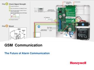
Check Signal Strength 9VAC 15VA NOTE: It is extremely important that you select a suitable mounting location that allows for adequate signal strength!!!
Wiring for ECP and 4204 modes 9VAC 15VA NOTE: AC Power must be applied on 1 and 2.
Wiring for ECP on a LynxR-i The LynxR-I series panels provide the primary and backup power for the GSM radio. Do Not Connect the 7845GSM internal battery or the GSM power transformer. NOTE: DC Power is supplied from LynxR-i panel.
Wiring Zone 1 input to a LynxR trigger output 9VAC 15VA Program Trigger as V- and enable Lynx Panic NOTE: AC Power must be applied to terminals 1 and 2 on 7845GSM.
Programming and Registration • There are several options to program and register the GSM radio: • Log on to Alarmnet Direct website and enter the appropriate radio and account information • https://services.alarmnet.com/alarmnetdirect/ • Program and register using the 7720p program tool. • Contact your Central Station • Call Alarmnet Registration at 800-222-6525 • Select option 1 for Technical Support, then press 1 for Alarmnet GSM device registration. You must have an account number (provided by your Central Station) and be able to provide radio MAC and CRC to proceed with registration.
Programming: Using the 7720p You must have AC power on terminals 1 and 2 for 7720p to work.
Programming Basics: Using the 7720p Plug in 7720P programmer and press Enter key • Press Enter to accept entries Use the up/down arrow keys to scroll through the programming questions without changing any values. Perform a Shift function by pressing Shift key and then the appropriate key. Strt Prog Mode? Y/N_ Press Shift & Y
Programming Options Enter Password Program 7845? Y/N Press Shift & Y Create Password? Y/N
Programming Options Options: ECP Zone Triggers 4204 EMU 2 4204s (Use the space key to scroll through options) Device Mode? ECP Primary City ID? (??) Acct info provided by your Central Station Primary CS ID? (??) Primary Sub ID? (????)
Programming Options 2ND CS Y/N? Option to use 2nd CS reporting only available on High-End panels (polling loop panels) 2ND City ID? (??) 2ND CS ID? (??) 2ND Sub ID? (????)
Programming Options Device Address (03) Enable DW Y/N (N) High-end Panels Only (polling loop) If Yes Direct Wire Address (28)
Programming Mode Supervision 24 hours • Options are: • None • 24 Hours • 30 days • Note: This feature does NOT enable a test report to be sent to the Central Station Old Alarm Time (10 Minutes) GSM Flt Time (60 mins) Flt Rel On Y/N (N)
Programming Mode Pwr Loss Rpt (Y/N) (Y) Disable these reports if installing on the LynxR-I (ECP) 1-3 hours of loss Low Bat Rpt (Y/N) (Y) Tamper Rpt (Y/N) (Y)
Programming Mode Zones 6 & 7 are available in ECP mode Enable Zn 6 (Y/N) (N) Zn 6 Trigger Type (V+) Restore Zn 6 (Y/N) (N) Invert Zn 6 (Y/N) (N) Delay Zn 6 (secs) (00) Repeat for zone 7 if required
Zone Mode • When the GSM is programmed for zone mode, there are six input zones available. • The first zone input (TB1, pin 5) can detect a pulsed signal (reported as zone 1) or a steady signal (reported as zone 2). • When using zone trigger mode, messages are sent in ADEMCO high-speed format.
Zone Mode Programming Options Trip Inputs 1or2 w/Bell out (N) • Enable this option when wiring zone 1/2 input (terminal 5) to control panel positive bell output. • This will help prevent false alarms caused by supervision voltage on the bell circuit. • This will also prevent the radio from causing bell circuit faults on the control panel. • Note: Enabling this feature will raise the trip voltage on zones 1, 2, and 3 from 2VDC to 5VDC. This option should not be enabled with negative trigger inputs on zones 1, 2, or 3.
Zone Mode Programming Options Zn1 Trigger Type (V+) This selects the triggering method for this zone input. Options are: (V+), (V-), or (EOLR) • If zone is set for (V+), the zone will report an alarm when voltage input is 2VDC-14VDC. • Trigger levels above 14VDC may damage the unit and trigger levels below 2VDC may not trigger the zone. • Remember: Enabling “Trip Inputs w/Bell out” increases minimum • trigger requirement for zones 1, 2, and 3 to 5VDC.
Zone Mode Programming Options Zn1 Trigger Type (V+) This selects the triggering method for this zone input. Options are: (V+), (V-), or (EOLR) • If the zone is set to (V-), the negative triggering voltage must be less than 1.0VDC. • If the zone is set to (EOLR), the zone will report an alarm when the EOLR is removed from the zone. • Recommended EOLR is 2K ohms.
Zone Mode Programming Options Restore Zn1 Y/N (Y) This enables the zone to report when it is restored. Delay Zn1 (secs) (00) This option defines any delay in reporting for this zone input (from 0 to 15 seconds). This option will disable this zone from reporting unless the conditional zone is triggered. (The conditional zone is zone 7 when radio is in zone mode.) Rpt Zn1 ONLY if Armed (N)
Zone Mode Programming Options This option inverts the alarm and normal states of the zone trigger. Invert Zn2 Y/N (N) This option is enabled only when radio is connected to a Lynx, LynxR, or LynxR-EN. This enables a silent panic alarm to be sent when a single pulse is detected on zone 1. Lynx Panic Y/N (N)
7845I-GSM Programming Options • Basically the same as the previously discussed “GSM flt time.” In the event there is loss of contact with the network over the Ethernet connection, enter the time delay before the 7845i-GSM notifies the Central Station of the problem. • IP failure will always be reported as “Primary Communication Path Failure” IP Flt Time (60 mins) • Programming options are: “Neither Fault” or “Both IP and GSM Faults.” • If “Both IP and GSM Faults” is selected, the device will notify the control panel (via ECP bus or GSM fault relay) if both communication paths fail. Notify Panel Of (Neither Fault)_
7845I-GSM Programming Options • If enabled, all messages (including AlarmNet network supervisory messages) are sent over GSM network in the event of an internet failure. • If disabled, all messages (except AlarmNet network supervisory messages) are sent over GSM network in the event of an internet failure. GSM Rollover Y/N (Y)_ • If enabled, the 7845i-GSM sends a supervision ping over the GSM network once a day to verify backup communication path. • A “secondary communication path loss” message is generated if the message is not successfully delivered. GSM 24Hr Tst Y/N (N)_
7845I-GSM Programming Options Use DHCP Y/N (Y)_ DHCP dynamically allocates the IP addresses (recommended). If you select “No,” then you must program the following fixed (static) IP addresses: NIC IP Address: 255.255.255.255_ Gateway IP Addr: 255.255.255.255_ Subnet Mask: 255.255.255.255_ DNS Server IP Addr: 255.255.255.255_
7845I-GSM Programming Options Enable Pwr Save (Y)_ For 24 UL battery backup requirement, this feature must be enabled, or the unit must be powered by an appropriate UL listed UPS. What does it do? If the feature is enabled, the communicator’s NIC card will power down and will power up every 20 seconds to send a test ping (to test internet path) then power down again. The NIC will also power up anytime the unit needs to transmit information over the internet. If connectivity problems occur with certain routers or switches, disable this option.
New Registration (Radio on New Account) After exiting programming mode on the 7720p, you may register the radio by hitting the Shift key, then the “up” arrow. Shift Registering… Registration Success
Replacement Registration • When registering a replacement radio on an active account, a pin number must be entered. After exiting programming mode, select the “down” arrow key. You will be prompted to enter a pin. • Enter PIN and hit the Enter key to proceed with registration. • If replacing a C radio, enter the last four digits of the min number. • If replacing a GSM with another GSM, a PIN must be generated by your Central Station. Enter PIN# Registering… Registration SUCCESS
GSM CommunicationProgrammerless Registration:Using Alarmnet Direct
Programmerless Registration Preliminary Steps Required Before Registration • Before registering, you must have the following information available: • CITY number • CS number • RADIO SUBSCRIBER number • DEVICE MODE • Daily or Monthly Supervision • MAC Address from 7845GSM Radio • MAC CRC number from the 7845GSM Radio • City number, CS number, and Radio Subscriber number is assigned by your Central Station
Programmerless Registration Steps Required to Enter Data • Log into AlarmNet Direct using your user name and password. https://services.alarmnet.com/AlarmNetDirect • To program a radio on a NEW account, select “Program New Device GSM/I” • To replace a “C” radio with a GSM, select “Replace C Device” • To replace a GSM with another GSM, select “Replace Other Device”
Programmerless Registration • Enter the radio’s information • CITY number • CS number • SUBSCRIBER number • Supervision Rate • MAC number • CRC number • Confirm the Device Mode, and if using ECP with device address 03 click Done.
Programmerless Registration AlarmNet C Replacement Enter 10 digit MIN number from old C Radio
Programmerless Registration AlarmNet GSM Replacement Enter PIN number generated by your Central Station
Programmerless Registration Important Note About Programmerless Replacements! • The PIN is only transferred to the 7845GSM device on the first data transfer attempt. • If your device fails to register, take the following steps using AlarmNet Direct. • Delete the account from “Show Programmed Devices”. • Add the account back using “Replace C” or “Replace Other Device”. • From the “Show Programmed Devices” page, execute the SEND DATA command and get confirmation of the data transfer by refreshing the page. • After current date and time are showing in the “Transferred” column, execute the “Register” command. • Following these steps will ensure the PIN is transferred to the device. Remember, If the device fails to register the first time, the PIN will be reset to FFFF and will not be accepted by the AlarmNet servers.
Programmerless Registration Selecting “Done” sets programming to default values, which is ECP Mode, Device Address 03. • If the installation requires you to change any programming option from the default value, select “Advanced Programming”.
Programmerless Registration Screenshot of “Advanced Programming” screen