Enhancing RHIC Collimation System: Loss Limitations and Solutions
350 likes | 452 Views
Explore RHIC's history, upgrade, operational limits, beam dumps, soil activation, and the collimator system's evolution for effective beam control and safety.

Enhancing RHIC Collimation System: Loss Limitations and Solutions
E N D
Presentation Transcript
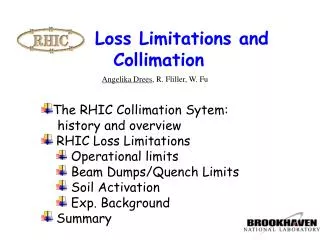
Loss Limitations and Collimation • The RHIC Collimation Sytem: • history and overview • RHIC Loss Limitations • Operational limits • Beam Dumps/Quench Limits • Soil Activation • Exp. Background • Summary Angelika Drees, R. Fliller, W. Fu
RHIC Collimator Configuration • RHIC was originally built with a 1-stage collimation system only: • 1 dual plane h/v scraper with 45 cm copper jaws, linear motion in both planes, skew motion only in horizontal • 1 bent crystal collimator for studies in 1 ring (yellow) only • The system was upgraded after the 2003 run because of high experimental backgrounds and gap cleaning demands. Crystal approach proved non sufficient.
RHIC overview: collimation system 2004 and upgrade 2000-2003: 1-stage system including bent crystal in 1 ring 2004: Traditional 2-stage system with 2 horizontal and 1 vertical secondary collimators 2005: Traditional 2-stage system with 2 horizontal and 2 vertical secondary collimators New blue 2ndary vertical collimator (v2) (capped area) New yellow 2ndary vert. Collimator (v2)
Collimator Section Layout In the shutdown 2003-2004 the collimation system was upgraded to a conventional 2-stage system including new individual secondary collimators for both planes. The new system was first used in the run 2004 for both, Au and protons.
Collimator Design 45 cm copper jaws One side only Rotatable, positioning: few mm H H V cross-section of the primary collimator (dual plane)
Crystal Collimation Attempt during Fill 3061 (Au) … If you want to know why we pulled out the crystal and installed traditional secondaries … • STAR “Yellow Halo” signal during Crystal Collimation attempt • scraper is closer to the beam toward the bottom of graph • crystal is at 13.6 mm from beam center and channeling • Scraper alone is more effective than the crystal and scraper together
Loss Limitations • Operational limit: keep allowable loss budget (radiation safety), monitored hour by hour • Quench limit: • magnet quenches due to accidental local losses during ramp/store => BLMs • magnet quenches at beam dump due to debunched beam => gap cleaning • Soil activation (not under radiation protection), depends on integrated yearly losses • Experimental backgrounds: need ‘clean’ beams to allow good signal/noise ratio in experiments and keep false trigger rate small (dead time)
Operational Limits: Monitoring of Beam Loss/hour dirty dump alarm level is reset max. alarm level 1 hour After every dump (operational or accidental) all RHIC loss monitors are analyzed. If dump appears to be “dirty”, i.e. unmasked loss monitors register losses above a certain level, injection into RHIC will be blocked for 1 hour (see figure).
Loss Limitations • Operational limit: keep allowable loss budget (radiation safety), monitored hour by hour • Quench limit: • magnet quenches due to accidental local losses during ramp/store => BLMs • magnet quenches at beam dump due to debunched beam => gap cleaning • Soil activation (not under radiation protection), depends on integrated yearly losses • Experimental backgrounds: need ‘clean’ beams to allow good signal/noise ratio in experiments and keep false trigger rate small (dead time)
Accidental Local Losses: BLM thresholds Magnet quenches can be caused by fast (ms) type losses. => BLM trip levels (thresholds) • fill 4118 • fill 4198 • Continuous scraping/losses cause magnet quenches as well. Trip levels don’t help. • software integration • or collimators
Collimators as limiting Aperture during Store It is difficult to maintain limiting aperture position at all times – especially during ramp!
Collimator use during the Ramp • Losses around RHIC on 2 ramps during FY01 • top: beam scraping at abort kickers • center: scrapers inserted • bottom: lattice • Using the collimators reduced losses at abort kickers by x100
Loss Limitations • Operational limit: keep allowable loss budget (radiation safety), monitored hour by hour • Quench limit: • magnet quenches due to accidental local losses during ramp/store => BLMs • magnet quenches at beam dump due to debunched beam => gap cleaning • Soil activation (not under radiation protection), depends on integrated yearly losses • Experimental backgrounds: need ‘clean’ beams to allow good signal/noise ration in experiments and keep false trigger rate small (dead time)
Gap Cleaning: Motivation and Method • gap cleaning is necessary due to the extensive debunching of HI beams (quenching risk) • method: • debunched beam is excited transversely (continuously during the store: 1Hz) using damping kickers • the collimation system absorbs the large amplitude particles (in addition to halo) • debunched beam should be lost in collimator area, efficiency relies on collimator performance to avoid increase of exp. backgrounds
Excitation frequency for Cleaning default procedure: excite around betatron tune of bunched beam (measured automatically at the end of ramp) optional procedure: perform automated tune scan to find resonant tune of debunched beam and excite with this frequency
fill 4471, Feb. 06 2004 start of cleaning ~5 109 Cleaning ON vs. cleaning OFF: 56 x 56 yellow: cleaning off, started around 3:30 to allow clean beam dump blue: cleaning on, debunched beam is continuously excited and absorbed by collimators
1 Hz excitation on standard BLMs: Normal cleaning levels are < 1% of trip Level => acceptable
Remaining debunching with Cleaning ON: Debunching rate clearly correlated with bunch current at the beginning of the store. For 4h store length, an upper limit of 1.4*109 ions per bunch results to maintain less than 5*109 debunched beam at the end of store (for safe beam dump).
Loss Limitations • Operational limit: keep allowable loss budget (radiation safety), monitored hour by hour • Quench limit: • magnet quenches due to accidental local losses during ramp/store => BLMs • magnet quenches at beam dump due to debunched beam => gap cleaning • Soil activation (not under radiation protection), depends on integrated yearly losses RHIC has to operate such that leachate (from activated soil) cannot contain concentrations of 3H or 22Na that exceed 5% of the drinking water standard Method: either cap the collimator area (prevent leaching) or use removable soil samples inside tunnel near collimators/dumps to monitor activation level. 22Na is easily measured.
Fill 4581: Au ions (100 GeV), blue gap cleaning was off The debunched beam is lost at the collimators: deb.rate = 2*10^7 ions/min loss rate (total beam) is: loss rate = 3*10^7 ions/min (lost anywhere: triplets, dump ...) total: 2-5*10^7 ions/min
Fill 4471, Feb. 06 2004, Au ions, 100 GeV The debunched beam is lost at the collimators: deb.rate = 2.3*10^7 ions/min loss rate (total beam) is: loss rate = 3*10^7 ions/min total (at collimators): 2.5-5*10^7 ions/min
Fill 4870, Mar 24 2004, Au ions, 100 GeV The debunched beam is lost at the collimators: deb.rate = 2.4*10^7 ions/min loss rate (total blue beam) is: 3*10^7 ions/min loss rate (total yellow beam) is: 8*10^7 ions/min total (at blue collimators): 2.5-5*10^7 ions/min total (at yellow collimators): 2.5-10*10^7 ions/min
Beam losses with proton beams Typical “bad” store: Loss rate: 10 10^11 = 5 10^9 p/min
Assumptions for Soil Activation Calculation • Au Operation: • total loss/min (from gap cleaning): 2*107 ions/min • assume all is lost at collimators, 10% at new V2 -> 2*106 ions/min during the store • assume average of 100 h/week at store (best week last run) • add 0-3 106 ions/min @ v2 => 2-5*106 ions/min • proton Operation: • total loss/min (from bad lifetime store during high intensity run): 5*109 p/min • assume all is lost at collimators, 10% at new v2 -> 5*108 p/min during the store • assume average of 80 h/week at store (best avg. last run)
Calculate Soil Activation (Na-22) from Loss Data Calculate for v2: given the assumptions and using an estimation with the bare collimator/no shielding (there is some concrete shielding @ v2), for Na-22, assuming 15 weeks for each of the Au and proton ions (ie. 30 weeks in total) we get: 8.7 (18) pCi/l and 11.0 pCi/l for the case of Au-ions and protons respectively. This adds up to 19.7 (29) pCi/l (after 1year), which is just the same (or x1.5 of) the 5% drinking water limit (20 pCi/l) for Na-22. Compare with Measurement (from soil sample): activation level at primary collimator calculated: 200 pCi/l. measured: 13 pCi/l assuming 100% of all losses at primary collimator is conservative the 15+15 weeks of running is conservative the operating efficiency is overestimated distance collimator-soil is underestimated
Loss Limitations • Experimental backgrounds: need ‘clean’ beams to allow good signal/noise ratio in experiments and keep false trigger rate small (dead time). • Collimator positioning should be reliable and efficient for background reduction • Time at the beginning of the store is precious because this has the highest luminosity -> Collimation and positioning of collimators should be FAST (and precise!)
Collimation during Fill 1759 (Au) • FY01 run has low beam current intensities • 1-stage system • only PHENIX benefits (some) from collimation • there is generally no/little need for collimation during the FY01 run
Collimation during Fill 3094 in FY03 (d-Au) • All experiments but PHOBOS benefit from collimation • vertical scraper retraction (vert. lines) clearly raises background • reduction rates are between 2 and 5
Automatic Steering Algorithm • RHIC has 5 jaws per ring, most • allow both, linear motion and • angular motion (to parallelize • with beam). Potentially time • consuming! => 18 degrees of freedom (+ 4 more next run) Requires automation (3 steps): • Move to STDBY position (based on BPM readings) • Move Closer to beam (based on loss monitor feedback, serial) • Remove Halo/Store (based on lattice functions, parallel)
Collimation during Fill 4854 (Au) in the blue ring Serial collimator steering (mode: Move Closer), following parallel mode does not improve backgrounds. Vertical lines denote when each collimator moves. Background improvement approx. x6. Note: secondary vertical collimator quite efficient.
Collimation during Fill 4436 (Au) Parallel collimator steering (mode: “Store”), using lattice fct. and assumed emittances. Vertical lines denote when collimators start and stop moving simultaneously. Background improvement approx. x10. Note: procedure stops automatically when desired background levels are reached.
Compare RHIC data from 1-stage and 2-stage collimation system Fill 3254 1-stage Fill 4854 2-stage
Comparison of Background Reduction Rates Average ratio of uncollimated to collimated background for the STAR and PHENIX detectors (sensitive to beam direction) over 6 stores in 2003 and 2004. In both cases PHOBOS had a b* of 3m.
Summary • Operational Limit • about 1 normal ‘fill’ /hour in uncontrolled areas • Magnet Quenches • store/ramps: BLM thresholds pull permit (fast and slow modes) • beam dump: continuous gap cleaning • Soil activation • maintain 5% of DWS (i.e. 20 pCi/l 22Na) by caps or soil sample monitoring in uncapped areas • Exp. Background • traditional 2-stage collimation system achieves average background reduction of x10