Digital Modulation
Digital Modulation. Contents:. 1.introduction Signal space representation of signals. Signal space model of digital communication system. Different modulation schemes. Points of comparison bet each mod scheme. 2-Binary modulation techniques 3-quadrature modulation techniques


Digital Modulation
E N D
Presentation Transcript
Contents: • 1.introduction • Signal space representation of signals. • Signal space model of digital communication system. • Different modulation schemes. • Points of comparison bet each mod scheme. • 2-Binary modulation techniques • 3-quadrature modulation techniques • 4-M-ary modulation techniques • 5-comparing different scheme • Power spectra. • Probability of error. • Bandwidth efficiency. • 6-bit vs. symbol error probabilities • 7-applications
Why modulate? • Antenna’s length • Multiplexing • Main idea: shifting(keying) the amplitude/frequency/phase of a high frequency carrier.
Modulator: • In digital communication : • modulating wave :binary data/M-ary encoded version of it • Carrier: usually sinusoidal wave • Hybrid modulation: Both amplitude and phase of carrier are combined to produce APK • Demodulator-receiver: • Coherent vs. non coherent detection • Coherent : • exact replicas of possible arriving signals are available at receiver ( exact knowledge of the carrier’s wave reference) • “receiver is phase locked to the transmitter • autocorrelator • Non coherent: • cross correlating the received signal with each one of he replicas and then make a decision made on comparisons with preselected threshold’s • Complexity increase while Pe decreases. • Trade offs: • Multitude of modulation/detection schemes • Trade off bet. Primary communication resources • transmission power • channel bandwidth
Design Goals: • max data rate • min Pe • min Pt • min BW • max resistance to noise • min circuit complexity • But Conflictions may occur : 1-power and bandwidth 2-data rate and probability of error Bit vs symbol: • M_ary signaling: modulator produces one of available set of M=2^m distinct signals in response to m bits of source data.
1- Signal space representation of signals • Concept of basis: • The set of basis vectors {e1, e2, …, en} of a space are • chosen such that: • Should be complete or span the vector space: any vector a • can be expressed as a linear combination of these vectors. • Each basis vector should be orthogonal to all others • Each basis vector should be normalized: energy=1 • A set of basis vectors satisfying these properties is also said to be a complete orthonormal basis • In an n-dim space, we can have at most n basis vectors • Basic idea: • representation of M energy signals {s(t)} as a linear combinations of N _orthonormal basis functions • signals used in communications can be expressed and visualized graphically • Let φ1(t), φ2(t),…., φn(t) be n signals • Consider a signal x(t) and suppose that • If every signal can be written as linear combination of (φ1(t), φ2(t),…., φn(t)) basis functions then we have a n-dim signal space
Procedure: • If • method • If inspection does not work we can use analytical method called Gram_shmidt method
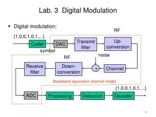
Signal space model of a digital comm. System: • Transmitter: Message source: emits one symbol every t seconds Vector transmitter: each signal si(t) corresponds to a symbol and using previous theorem each signal can be represented as a linear combination of the basis of the system . i.e. si=[si1 ; si2;… SiN ]
Modulator : The modulator target is to multiply the vector corresponding to the signal to be transmitted with the basis of the signal and transmits the signal Si(t)through the channel.
Channel : • AWGN is added to the signal and it can be viewed as adding vector W to the signal vector S producing the received signal vector X=S+W
Receiver: • Its task will be observing the received message x(t) for T seconds and make the best estimate of si(t) or equivalently the symbol mi • This occurs in 2 stages: 1-detector: takes x(t) and produces a vector of random Variables X 2-vector receiver : by using an observation vector x(which is a sample value of X),prior knowledge of si(t) the vector receiver produces an estimate of mi *Think of this
how does error (bit flip occur) and why does the probabilities vary from one model to another?
Coherent Binary FSK In a binary FSK system, symbols 1 and 0 are distinguished from each other by transmitting one of two sinusoidal waves that differ in frequency by a fixed amount. A typical pair of sinusoidal waves is described by
Thus symbol 1 is represented by s1(t), and symbol 0 by s2(t),the signals s1(t) and s2(t) are orthogonal. (a) binary FSK transmitter when we have symbol 0 at the input, the oscillator in the upper channel is switched off, and the oscillator in the lower channel is switched on, with the result that frequency f2 is transmitted. The two frequencies f1 and f2 are chosen to equal integer multiples of the bit rate 1 /Tb.
(b) coherent binary FSK receiver. • In order to detect the original binary sequence given the noisy received wave x(t), we may use the receiver shown . • It consists of two correlators with a common input, which are supplied with locally generated coherent reference signals φ1(t) and φ2(t). • The correlator outputs are then subtracted, one from the other, and the resulting difference, l, is compared with a threshold of zero volts. If l > 0, the receiver decides in favor of 1. On the other hand, if l < 0, it decides in favor of 0. The average probability of symbol error for coherent binary FSK is
C o h e r e n t B i n a r y P S K • In a coherent binary PSK system, the pair of signals, s1(t) and s2(t), used to represent binary symbols 1 and 0, respectively, are defined by
• In order to ensure that each transmitted bit contains an integral number of cycles of the carrier wave, the carrier frequency fc = nc/Tb for some fixed integer nc. • A pair of sinusoidal waves that differ only in a relative phase-shift of 180 degrees.
(b) coherent binary PSK receiver • To detect the original binary sequence of 1s and 0s, we apply the noisy PSK wave x ( t ) (at the channel output) to a correlator, which is also supplied with a locally generated coherent reference signal φ1(t), as in Figure 4.2b. • The correlator output, x1, is compared with a threshold of zero volts. If x1 > 0, the receiver decides in favor of symbol 1. If x1 < 0, it decides in favor of symbol 0. • The average probability of symbol error for coherent binary PSK equals
Quadriphase-shift Keying • As with binary PSK the information carried by the transmitted wave is contained in the phase. • In quadriphase-shift keying (QPSK), the phase of the carrier takes on one of four equally spaced values, such as π /4, 3π/4, 5π/4 and 7π/4 as shown by Using a well-known trigonometric identity, we may rewrite Eq.
In a QPSK system, we note that there are two bits per symbol. This means that the transmitted signal energy per symbol is twice the signal energy per bit : • So The average probability of symbol error for coherent binary QPSK equals
(a) QPSK transmitter • This binary wave is divided by means of a de-multiplexer into two separate binary waves consisting of the odd- and even numbered input bits. •Example: if (01) is the input so the 1st bit (odd) is {0} and the 2nd bit (even) is {1}
• The QPSK receiver consists of a pair of correlators with a common input and supplied with a locally generated pair of coherent reference signals φ1(t) and φ2(t) as in Figure . The correlator outputs, x1 and x2, are each compared with a threshold of zero volts. • If x1 > 0, a decision is made in favor of symbol 1 for the upper or in-phase channel output, but if x1 < 0 a decision is made in favor of symbol 0. • If x2 > 0, a decision is made in favor of symbol 1 for the lower or quadrature channel output, but if x2 < 0, a decision is made in favor of symbol 0. • Finally, these two binary sequences at the in-phase and quadrature channel outputs are combined in a multiplexer to reproduce the original binary sequence at the transmitter input with the minimum probability of symbol error.
Non-coherent Binary Mod. Techniques: A digital communication receiver with no provision make for carrier phase recovery is said to be non-coherent. Non-coherent Orthogonal Modulation: Scheme. For a binary signaling scheme that involves the use of two signals which are orthogonal with equal energy.
the received signal x(t) can be expressed as follows • The receiver tries to discriminate between s1(t) and s2(t), regardless of the carrier phase. This goal can be achieved by the following receiver structure:
A non-coherent matched filter may be viewed as being equivalent to a quadrature receiver, as illustrated below. The quadrature receiver itself has two channel • Let φ1(t) and φ 2(t) be the orthonormal set of s1(t) and s2(t) and Ǿ(t) be the version of φ(t) that results from shifting the carrier phase by -90 degrees(Hilbert Transform)
The average probability of error for the non-coherent receiver • where E is the signal energy per symbol and N0/2 is the noise spectral density.
Non-coherent BFSK • For the binary FSK case, the transmitted signal is
Thus the non-coherent binary FSK is a special case of non-coherent orthogonal modulation with T=Tb and E=Eb, where Tbis the bit duration and Ebis the signal energy per bit.
Differential Phase-shift Keying (DPSK) • Transmitter’s two operations: (1) differential encoding of the input binary sequence and (2) phase-shift keying • Generation of DPSK: For an input binary sequence {bk},a differential encoded sequence{dk} is made as follows:
DPSK is another example of non-coherent orthogonal modulation, when it is considered over two bit intervals. Where T = 2Tband E = 2Eb.
Note that DPSK is 3dB poorer than BPSK, however it is much easier to implement as it doesn’t require phase synchronization.
M-ARY MODULATION TECHNIQUES • we send any one of M possible signals S1(t), S2(t), ………, SM(t) during each signaling interval of duration T • The requirement is to conserve bandwidth at the expense of both increased power and increased system complexity • When the bandwidth of the channel is less than the required value, we resort to an M-ary modulation scheme for maximum bandwidth conservation • M-ary Phase-Shift Keying • If we take blocks of m bits to produce a symbol and use an M-ary PSK scheme with M=2n and symbol duration T=nTb • The bandwidth required is proportional to 1/(nTb) • The use of M-ary PSK provides a reduction in transmission bandwidth by a factor by a factor n=log2M
M-ary PSK • The phase of the carrier takes one of M possible values, namely, • A M-ary signal set is represented as , for • where T is the symbol duration and E is the signal energy per symbol. The carrier frequency where nc is a fixed integer. • each signal si(t) can be expanded in terms of the following two basis , • the signal constellation of M-ary PSK is two-dimensional. The M messages are equally spaced on a circle of radius and center at the origin
Example: octaphase-shift-keying (M=8) • The decision boundaries are shown as dashed lines.
The optimum receiver includes a pair of correlators with reference signals in phase quadrature. The two correlator outputs XI and XQ are fed into a phase discriminator that computes the phase estimated • w1 & w2 are samples of two independent Gaussian random variables of zero mean and common variance
Phase discriminator selects from the set of the signal whose phase is closet to the estimated The decision region is bounded by the threshold Probability of correct reception is therefore Where is the probability density function of the random variable The probability of symbol error is For large M and high values of
M-ary FSK • In an M-aryFSK scheme, the transmitted signals are defined by the carrier frequency where nc is a fixed integer The transmitted signals are of equal duration T and have equal energy The individual signal frequencies are separated by 1/2T hertz The signals are orthogonal For coherent M_ary FSK ,the optimum receiver consists of a bank of M correlators or matched filters. At the sampling time the receiver makes decisions on the largest matched filter output.
M_ary QAM (Quadrature Amplitude Modulation): • In this modulation scheme the carrier experiences amplitude and phase modulation. signal constellation for M=16
Transmitter • Receiver
The transmitted energy in Mary QAM is variable , as its instantaneous value depends on the particular symbol transmitted. Therefore the probability of error is expressed in terms of average value of the transmitted energy.
Power spectra of M_ary signals: PSK The symbol duration of M_ary PSK is defined by T=Tb log2M The base band power spectral density of M_ary PSK is given by: SB(f)=2Esinc2(Tf) SB(f)=2Eb log2M sinc2(Tb log2M f)
BANDWIDTH EFFICIENCY: • Our main objective is to maximize the bandwidth efficiency at a minimum practical expenditure of average signal power. • With the data rate Rb and the channel bandwidth B, we may express the bandwidth efficiency, as : Bandwidth Efficiency of M-ary PSK Signals: The bandwidth of M-ary PSK (B) is defined as the null-to-null bandwidth (contains most of the signal power).