Download
1 / 21
440 likes | 1.06k Views
Component Diagram. Component Diagram. Component diagram Show the structural relationships between components of a system Depicts how components are wired together to form larger components and or software systems Has a higher level of abstraction than a class diagram Created in DESIGN step

E N D
Component Diagram • Component diagram • Show the structural relationships between components of a system • Depicts how components are wired together to form larger components and or software systems • Has a higher level of abstraction than a class diagram • Created in DESIGN step • Component • Building block- usually implemented by one or more classes(or objects) at runtime • Large design unit - Can be implemented as replaceable module • May use “Interface” – replaceable or reusable • Provides interface to another component
Component Diagram • presents an early understanding of the overall system that is being built • Provide architectural overview to Implementation staff andstakeholders • Improve the level of understanding and communication • Help Implementation staff to make roadmap for implementation, and to divide/distribute workload
Modeling components and their relationship • Clients can envision the structure and the functionality in the finished system • Developers have a structure to work toward • Technical writers who have to provide documentation and help files can understand what they’re writing about • Your are ready for reuse
Component Notation (in UML 1.x) Shows relationship between two components. In UML 1.4, a component is represented as a rectangle with two smaller rectangles protruding from its left side.
Component Notation (in UML 2.x) • Interface • the formal contract of services the component provides to its consumers/clients • component offering service : uses provided interface • Component accessing service : uses required interface
interface • A set of operations that allow you to access a class’s behavior • a kind of a class that only has operations (with no implementation) • Classes inherit operations of interface and implement the interface
realization • Relationshipe between interface and class or between interface and component Implementing Object realization Defining Object
Dependency • An object or component use/execute another object or component
Provided/Required Interface • the Order component provides two interfaces: OrderEntry and AccountPayable, and the Order component requires the Person interface
Interface realization < interface and its realization >
< An interface Key (i) is realized by a component Calculator and (ii) is used by a component Robot>
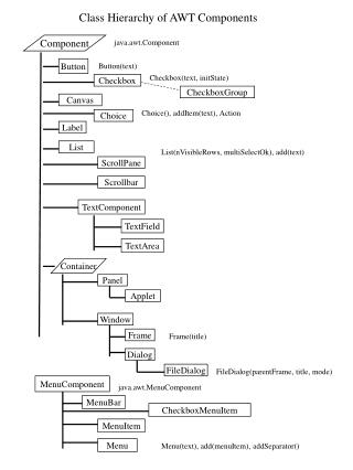
<<Interface>> ItemListener <<Interface>> ItemListener itemStateChanged() itemStateChanged() AWTEventMulticaster checkbox ItemListener dependency realization checkbox AWTEventMulticaster Component and Interface AWTEventMulticaster ItemListener AWTEventMulticaster Interface is defined in a rectangle
Component’s internal structure • When a component is composed of other components port • Port : ports provide a way to model how a component's provided/required interfaces relate to its internal parts • the OrderEntry port delegates to the Order component's OrderEntry interface for processing
Deployment Diagram • Showing • the structure of physical system • How the pieces of hardware connect to each other • Node • Hardware Item (computing resource) • Represented as cube • Connection • Connect two nodes • Doesn’t need to be wire or cable • Useful for modeling network