USE CASE
USE CASE . Object Oriented Approach and Technology. Unified Approach recommends the following process towards system development Analysis Identification of use cases Build object oriented analysis model using use case. Design Build object oriented design model using analysis model.

USE CASE
E N D
Presentation Transcript
Object Oriented Approach and Technology • Unified Approach recommends the following process towards system development • Analysis • Identification of use cases • Build object oriented analysis model using use case. • Design • Build object oriented design model using analysis model. • Implementation • Prototyping and developing the model in increments • Continuous testing The processes are repeated for all the functions till the system is fully developed.
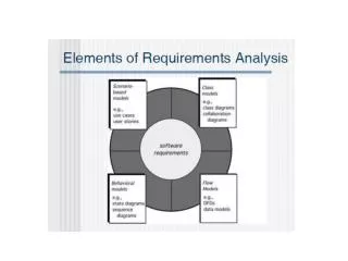
The Unified Modeling Language (UML) • Unified Approach advocates the use of standard object oriented modeling language called the UML. • UML provides standard notations for different OO models for better understanding • UML is a modeling language used to create an abstract system scenario by visualizing, specifying, constructing and documenting various components of the system into a representative models.
The Unified Modeling Language (UML) • Every UML diagram plays a unique contributory role in improving the understanding of the system. • The eight diagrams of UML are • Structural modeling • Use Case diagram • Static class diagram • Behavioural Modeling • Sequence diagram • Collaboration diagram • State Chart diagram • Activity diagram • Implementation Modeling • Component diagram • Deployment diagram
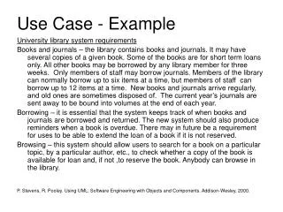
Use-Case Diagrams • A System runs through functions/processes. • A use case model/diagram is a graphical representation that captures all the functions (known as use cases) carried out in the system. • Use Case diagrams help developers to gain a clear understanding of the functional requirements of the system, without worrying about how to implement the requirements. • Use-Case modeling is done in the early stages of system development life cycle. 20.5
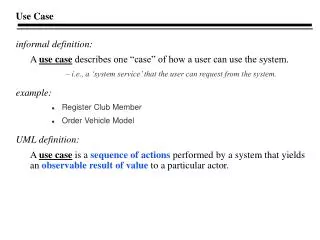
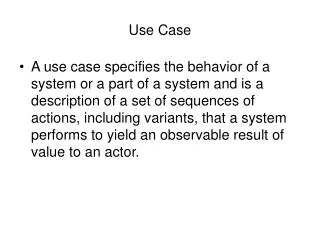
What is a Use case? • The processes in a systems are run by the users. • Each user has a role and responsibility in the system. • These processes are modeled in the use case and the situation in which the user interacts with the process is called scenario. • A use case describes the behaviour of a process under various conditions as the process in a system responds to request from principal users.
Elements of a Use Case Diagram Actors: • An actor is an external entity that interacts with the system. An actor portrays any entity (or entities) that exchange information with the system. An actor in a use case diagram interacts with a use case to accomplish a specific goal. • For example, for modeling a banking application, a customer entity represents an actor in the application. Similarly, the person who provides service at the counter is also an actor.
Elements of a Use Case Diagram • There is a difference between an actor and a user. • A user is anyone who uses the system. • An actor on the other hand, represents a role that a user can play. The actor’s name should indicate that role. • An actor is a type or class of users; a user is a specific instance of an actor class playing the actor’s role. • A same user can play multiple role. • As actors are outside the system, there is nor need to describe them in detail. • The advantage of identifying actors is that it helps us to identify the use cases( functions) they carry out. • It is not necessary that the user be a human being. It could be an organization or any other information system or hardware( e.g. barcode reader, card swiping machine etc.)
Elements of a Use Case Diagram An actor is shown as a stick figure in a use case diagram depicted "outside" the system boundary, as shown in Figure 1. Figure 1: an actor in a use case diagram << Actor >>
Elements of a Use Case Diagram • To identify an actor, search in the problem statement for business terms that portray roles in the system. For example, in the statement "patients visit the doctor in the clinic for medical tests," "doctor" and "patients" are the roles played and can be easily identified as actors in the system.
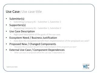
Elements of a Use Case Diagram Use case: • A use case in a use case diagram is a visual representation of a distinct functionality in a system. In other words, each use case must perform a distinct function. • As the first step in identifying use cases, you should list the discrete functions in your problem statement. Each of these functions can be classified as a potential use case.
Figure 2: use cases in a use case diagram The name of the use case can be listed inside the ellipse or just below it.
Elements of a Use Case Diagram • Figure 2 shows two uses cases: "Make appointment" and "Perform medical tests" in the use case diagram of a clinic system. As another example, consider that a process such as "manage patient records" can in turn have sub-processes like "manage patient's personal information" and "manage patient's medical information.“ • A use case can be stated as a present –tense verb phrase, containing the verb and the object of the verb e.g. compute gpa of student
Elements of a Use Case Diagram • System boundary: A system boundary defines the scope of what a system will be. A system cannot have infinite functionality. So, it follows that use cases also need to have definitive limits defined. A system boundary of a use case diagram defines the limits of the system. The system boundary is shown as a rectangle spanning all the use cases in the system.
Figure 3: a use case diagram depicting the system boundary of a clinic application
Elements of a Use Case Diagram • Figure 3 shows the system boundary of the clinic application. The use cases of this system are enclosed in a rectangle. Note that the actors in the system are outside the system boundary. The actors are connected to use cases with lines and that use cases are connected to each other with arrows • The system boundary is potentially the entire system as defined in the problem statement. But this is not always the case.
Relationships in Use Cases • Use cases share different kinds of relationships. A relationship between two use cases is basically a dependency between the two use cases. • Defining a relationship between two use cases is the decision of the modeler of the use case diagram. • Use case relationships can be one of the following:
Relationships in Use Cases • Include: When a use case is depicted as using the functionality of another use case in a diagram, this relationship between the use cases is named as an include relationship. • Literally speaking, in an include relationship, a use case includes the functionality described in the another use case as a part of its process flow. An include relationship is depicted with a directed arrow having a dotted shaft. The tip of the arrowhead points to the child use case and the parent use case is connected at the base of the arrow. The stereotype "<<include>>" identifies the relationship as an include relationship.
Relationships in Use Cases • For example, in Figure 4, you can see that the functionality defined by the "Validate patient records" use case is contained within the "Make appointment" use case. Hence, whenever the "Make appointment" use case executes, the steps defined in the "Validate patient records" use case are also executed.
Relationships in Use Cases • Extend: In an extend relationship between two use cases, the child use case adds to the existing functionality and characteristics of the parent use case. • Extend relationship is used to design handling exceptions. • An extend relationship is depicted with a directed arrow having a dotted shaft, similar to the include relationship. The tip of the arrowhead points to the parent use case and the child use case is connected at the base of the arrow. The stereotype "<<extend>>" identifies the relationship as an extend relationship, as shown in Figure 5.
Relationships in Use Cases • Figure 5 shows an example of an extend relationship between the "Perform medical tests" (parent) and "Perform Pathological Tests" (child) use cases. The "Perform Pathological Tests" use case enhances the functionality of the "Perform medical tests" use case. Essentially, the "Perform Pathological Tests" use case is a specialized version of the generic "Perform medical tests" use case.
Relationships in Use Cases • Generalizations: A generalization relationship is also a parent-child relationship between use cases. The child use case in the generalization relationship is an enhancement (specialization) of the parent use case. • In a use case diagram, generalization is shown as a directed arrow with a triangle arrowhead (see Figure 6). The child use case is connected at the base of the arrow. The tip of the arrow is connected to the parent use case.
Relationships in Use Cases • On the face of it, both generalizations and extends appear to be more or less similar. But there is a subtle difference between a generalization relationship and an extend relationship.
Relationships in Use Cases • When you establish a generalization relationship between use cases, this implies that the parent use case can be replaced by the child use case. On the other hand, an extend relationship between use cases implies that the child use case enhances the functionality of the parent use case into a specialized functionality. The parent use case in an extend relationship cannot be replaced by the child use case.
Relationships in Use Cases • Now, if we had defined this as an extend relationship between the two use cases, this would imply that the "Store patient records (computerized file)" use case is a specialized version of the "Store patient records (paper file)" use case. Hence, you would not be able to seamlessly (without effort) replace the occurrence of the "Store patient records (paper file)" use case with the "Store patient records (computerized file)" use case.
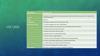
ATM Example • An ATM system will have a key operated switch that will allow an operator to start and stop the servicing of customers. • The ATM will serve on customer at a time. A customer will be required to insert an ATM card and enter a PIN both of which will be sent to the bank for validation as part of each transaction. If the PIN is not valid, then perform the use-case “invalid PIN”. • Whenever a customer inserts an ATM card in the card reader of an ATM, a transaction can be started. The customer will then be able to perform one of the following transactions • A customer must be able to make a cash withdrawal. • A customer must be able to make deposits to any account • A customer must be able to make transfer of money between any two accounts linked to the card. • A customer must be able to make a balance inquiry of any account linked to the card.
Example:Draw a use case diagram (specify the relationship if any) for a university registration system. Class registration , which is the basic flow (course number, section number, term, year) is carried out by the registration clerk. He checks whether the student has opted for registration of special classes (alternative flow). If yes, the Registration for special classes use case will be performed. Registering for a special class requires prior permission of the instructor in addition to the other steps carried out for a regular registration. In normal cases, only class registration would be performed, because students would have met the prerequisite requirements. However, in situations where a student has not taken one or more of the prerequisite, the Prereq course not completed use case is performed. Student billing is initiated by University office, which interacts with the student instances by mailing the tuition invoices.