Download

1 / 11
110 likes | 142 Views
Learn about stresses on inclined sections, stress elements, and formulas for compressive stress in non-uniformly heated bars. Understand stress analysis principles and solving for maximum permissible loads.

E N D
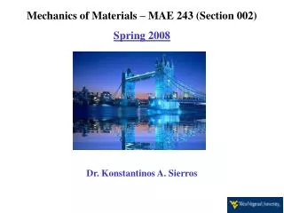
Mechanics of Materials – MAE 243 (Section 002) Spring 2008 Dr. Konstantinos A. Sierros
Problem 2.4-14 A rigid bar ABCD is pinned at point B and supported by springs at A and D (see figure). The springs at A and D have stiffnesses k1 = 10 kN/m and k2 = 25 kN/m, respectively, and the dimensions a, b, and c are 250 mm, 500 mm, and 200 mm, respectively. A load P acts at point C. If the angle of rotation of the bar due to the action of the load P is limited to 3°, what is the maximum permissible load Pmax?
Problem 2.5-5 A bar AB of length L is held between rigid supports and heated nonuniformly in such a manner that the temperature increase ΔT at distance x from end A is given by the expression ΔT = TB (x^3/L^3), where ΔTBis the increase in temperature at end B of the bar (see figure). Derive a formula for the compressive stress c in the bar. (Assume that the material has modulus of elasticity E and coefficient of thermal expansion .)
2.6: Stresses on inclined sections • Up to now we have considered normal stresses acting on cross-sections • Provided that the bar is prismatic, the material is homogeneous, the axial force P acts at the centroid of the cross-sectional area and the cross-section is away from any localized stress concentrations
2.6: Stress elements • Isolating a small element C (fig. 2-30 c) • We have a stress element (fog 2-31 a) • The only stresses acting are the normal stresses σx • Because it is more convenient, we usually draw a 2-D view of the stress element (fig. 2-31 b)
2.6: Stresses on inclined sections • In order to obtain a more complete picture, we need to investigate the stresses acting on inclined sections (plane pq fig. 2-32 a) • Uniform distribution of stresses as shown in figs 2-32 b and c
2.6: Stresses on inclined sections • We need to specify the orientation of the section pq. Define an angle θ between the x-axis and the normal n to the section • We need to find the stresses acting on the section pq • Load P, which is the stress resultant, can be resolved with respect to N and V • N is associated with normal stresses and V is associated with shear stresses
2.6: Stresses on inclined sections • Establish standard notation and sign convention • Normal stresses σθ are positive in tension and shear stresses τθ when they tend to produce counterclockwise rotation of the material where σx = P/A, in which σx is the normal stress on a cross-section
2.6: Stresses on inclined sections • Element A: The only stresses are the maximum normal stresses (θ = 0) • Element B: This is a special case where all four faces have the same magnitude normal and shear stress (σx/2)
2.6: Stresses on inclined sections The shear stress may cause failure if the material is much weaker in shear than in tension