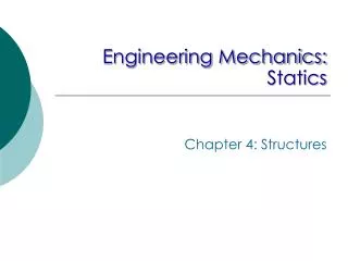
ME101-Basic Mechanical Engineering (STATICS) Structural Analysis
ME101-Basic Mechanical Engineering (STATICS) Structural Analysis. Textbook: Engineering Mechanics- STATICS and DYNAMICS 11 th Ed., R. C. Hibbeler and A. Gupta Course Instructor: Miss Saman Shahid. Simple Truss.

ME101-Basic Mechanical Engineering (STATICS) Structural Analysis
E N D
Presentation Transcript
ME101-Basic Mechanical Engineering(STATICS)Structural Analysis Textbook: Engineering Mechanics- STATICS and DYNAMICS 11th Ed., R. C. Hibbeler and A. Gupta Course Instructor: Miss SamanShahid
Simple Truss • A truss is a structure composed of slender members joined together at their end points. • The joints connections are usually formed by bolting or welding the ends of the members to a common plate, called a gusset plate.
Gusset plate Examples of Trusses Joints are often bolted, riveted, or welded. Gusset plates are also often included to tie the members together. However, the members are designed to support axial loads so assuming that the joints act as if they are pinned is a good approximation. Photo - Pin-jointed connection of the approach span to the San Francisco-Oakland Bay Bridge
A rigid truss will not collapse under the application of a load. • A simple truss is constructed by successively adding two members and one connection to the basic triangular truss. Simple Trusses • In a simple truss, m = 2n - 3 where m is the total number of members and n is the number of joints.
Example of Truss: The use of the metal gusset plates in the construction of these Warren trusses is clearly evident.
Planar Trusses • Planar trusses lie in a single plane and are often used to support roofs and bridges. The truss. • The truss ABCDE shown is an example of a typical roof-supporting truss. • The analysis of the forces developed in the truss members is two-dimensional. • In case of a bridge, the load on the deck is first transmitted to stringers, then to floor beams and finally to the joints B,C and D of the two supporting trusses. • When bridge or roof trusses extend over large distances, a rocker or roller is commonly used for supporting one end, e.g., joint E. this type of support allows freedom for expansion or contraction of the members due to temperature or application of loads.
Examples The roof truss shown is formed by two planar trusses connected by a series of purlins. Members of a truss are slender and not capable of supporting large lateral loads. Loads must be applied at the joints.
Examples of Trusses Roof trusses – Safeco Field in Seattle
Examples of Trusses Photo - Because roof trusses, such as those shown, require support only at their ends, it is possible to construct buildings with large unobstructed floor areas.
Design of a Truss • All loadings are applied at the joints. • Most structures are made of several trusses joined together to form a space framework. Each truss carries those loads which act in its plane and may be treated as a two-dimensional structure. • Bolted or welded connections are assumed to be pinned together. This assumption is satisfactory provided the center lines of the joining members are concurrent. • Forces acting at the member ends reduce to a single force and no couple. Only two-force members are considered. • When forces tend to pull the member apart, it is in tension. When the forces tend to compress the member, it is in compression.
Method of Joints • Dismember the truss and create a freebody diagram for each member and pin. • The two forces exerted on each member are equal, have the same line of action, and opposite sense. • Forces exerted by a member on the pins or joints at its ends are directed along the member and equal and opposite. • Because the truss members are all straight two-force members lying in the same plane, the force system acting at each joint is coplanar and concurrent. Therefore, moment equilibrium is automatically satisfied. At the joint (or pin). • And it is only necessary to satisfy ΣFx=0=ΣFy , to ensure equilibrium. • Always assume the unknown member forces acting on the joint’s free-body diagram to be in tension (pulling) on the pin. If this is done, then numerical solution of the equilibrium equations will yield positive scalars for members in tension and negative scalars for the members in compression.
Zero-Force Members • Truss analysis using the method of joints is greatly simplified if we first determine those members which support no loading. • These zero-force members are used to increase the stability of the truss during construction and to provide support if the applied loading is changed. • The zero-force members of a truss can generally be determined by the inspection of each of its joints. • As a general rule, if only two members form a truss joint and no external load or support reaction is applied to the joint, the members must be zero-force members. • If three members form a truss joint for which two of the members are collinear, the third member is a zero-force member provided no external force or support reaction is applied to the joint.
Space Trusses • An elementary space truss consists of 6 members connected at 4 joints to form a tetrahedron. • A simple space truss is formed and can be extended when 3 new members and 1 joint are added at the same time. • In a simple space truss, m = 3n - 6 where m is the number of members and n is the number of joints. • Conditions of equilibrium for the joints provide 3n equations. For a simple truss, 3n = m + 6 and the equations can be solved for m member forces and 6 support reactions. • Equilibrium for the entire truss provides 6 additional equations which are not independent of the joint equations.
Space Trusses Photo – Three-dimensional or space trusses are used for broadcast and power transmission line towers, roof framing, and spacecraft applications, such as components of the International Space Station.
Frames and Machines • Frames and Machines are two types of structures which are often composed of pin-connected multiforce members, that is, members that are subjected to more than two forces. • Frames are generally stationary and are used to support loads, whereas machines contain moving parts and are designed to transmit and alter the effect of forces. • The forces acting at the joints and supports can be determined by applying the equations of equilibrium to each member. • Examples 6.9, 6.10, 6.11, 6.12 and 6.13
Some frames may collapse if removed from their supports. Such frames can not be treated as rigid bodies. • A free-body diagram of the complete frame indicates four unknown force components which can not be determined from the three equilibrium conditions. • The frame must be considered as two distinct, but related, rigid bodies. Frames Which Cease To Be Rigid When Detached From Their Supports • With equal and opposite reactions at the contact point between members, the two free-body diagrams indicate 6 unknown force components. • Equilibrium requirements for the two rigid bodies yield 6 independent equations.
Equations of Equilibrium (frame or machine) • Provided the structure is properly supported and contains no more supports or members than are necessary to prevent its collapse, then then the unknown forces at the supports and connections can be determined from the equations of equilibrium. • If the structure lies in the x-y plane, then for each free-body diagram drawn the loading must satisfy ΣFx=0=ΣFy and ΣMo=0
Machines are structures designed to transmit and modify forces. Their main purpose is to transform input forces into output forces. • Create a free-body diagram of the complete machine, including the reaction that the wire exerts. • The machine is a nonrigid structure. Use one of the components as a free-body. • Taking moments about A, Machines • Given the magnitude of P, determine the magnitude of Q.
References: • Engineering Mechanics- STATICS and DYNAMICS, 11th Ed., R. C. Hibbeler and A. Gupta, Prentice Hall. • Vector Mechanics for Engineers, Statics, 7th Ed., Ferdinand P. Beer, E. Russell Johnson, Jr.,McGraw-Hill , Lecture notes by J. Walt Oler (Texas Tech University)