Download
1 / 53
540 likes | 656 Views
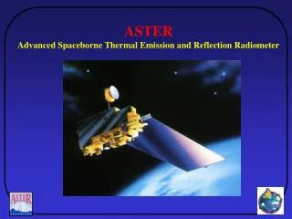
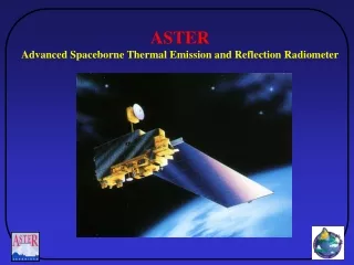
Lecture 9 Derivation of the EM signal detected by a spaceborne radiometer 23 March 2009. Part II Remote Sensing using Reflected Visible and Infrared Radiation 6 02-Mar Campus Closed Ch 17.1-17.3 04-Mar 7 Surface reflectance – Land Surfaces I

E N D
Lecture 9 Derivation of the EM signal detected by a spaceborne radiometer23 March 2009
Part II Remote Sensing using Reflected Visible and Infrared Radiation 6 02-Mar Campus Closed Ch 17.1-17.3 04-Mar 7 Surface reflectance – Land Surfaces I 05-Mar Lab 2 Contrast stretching and DN to reflectance conversion in ENVI 7 09-Mar 7 extended, 8 Surface reflectance 11-Mar 8 Water Bodies Ch 19.1-19.6 12-Mar Lab 3 Visual Analysis and High Resolution Visual Analysis 8 16-Mar Spring Break 18-Mar 9 23-Mar 9 Detection of EM Radiation by a Vis/IR Radiometer 25-Mar 10 Multispectral Remote Sensing Systems I Ch 6,21 26-Mar Lab 4 Reflectance Spectra Compared to RS Images and Veg Index 10 30-Mar Multispectral Remote Sensing Systems II Ch 6,21 01-Apr 11 Multispectral Remote Sensing Data Analyses I Ch 12,17.9-17.10 02-Apr Lab 5 Image Classification 11 06-Apr 11 Multispectral Remote Sensing Data Analyses II 08-Apr Exam 2 – will cover material presented in Lectures 7-11 09-Apr Lab 6 Multi-temporal change detection
Source of Figures The figures used in today’s lectures are from Jensen, J.R., Remote Sensing of the Environment - An Earth Resource Perspective, 2nd Edition, 592 pp., Prentice Hall, Upper Saddle River, NJ, 2007.
Key components of VIS/RIR remote sensing Lecture 2 – Energy emitted from sun based on Stephan/Boltzman Law, Planck’s formula, and Wein Displacement Law Fig. 1 VIS/RIR Satellite Lecture 9 – EM energy arriving at the sensor EM energy Lectures 3 EM Energy interacts with the atmosphere going to and coming from the earth’s surface Lectures 7-8 EM energy reflected/scattered from Earth’s Surface
Fig. 2 • The conceptual model presented by Jensen in Figure 2-22 is the focus of today’s lecture • This figure presents all the sources of EM energy that are detected by a remote sensing system operating in the VIS/RIR region of the EM Spectrum
Key Points • Terms describing EM radiation for remote sensing a. Radiant Flux b. Radiant Flux Density • Irradiance • Exitance c. Radiance • Model of total EM radiance detected by a spaceborne radiometer
Radiant Flux - • The fundamental unit to measure electromagnetic radiation is radiant flux • Defined as the amount of energy that passes into, through, or off of a surface per unit of time • Radiant flux is measured in Watts (W)
Radiant Flux Density Radiant flux density is simply the amount of radiant flux per unit area Radiant flux density represents the amount of EM energy coming from the area represented by a pixel Radiant flux density = /area
Irradiance versus Exitance • Irradiance (E) is the radiant flux density that is incident on a surface • Exitance (M) is the radiant flux density that exits a surface
Irradiance - E Irradiance is the amount of incident radiant flux per unit area of a plane surface in Watts / square meter (W m –2 ) Fig 2-20 in Jensen
Exitance - M • Exitance is the amount of radiant flux per unit area leaving a plane surface in Watts per square meter (W m –2 ) Fig 2-20 in Jensen
Irradiance onto the pixel Fig. 3 Detection by the sensor and conversion to a DN Exitance off the pixel • Irradiance and exitance are important because they define the amount of EM energy that is directed towards and coming from the area on the ground being detected by the remote sensing system • They are directly related to the DN recorded for a specific pixel (which represents a specific amount of EM energy)
Sources of Exitance (M) 1. Reflected irradiance M = r E, Where r is the hemispherical reflection coefficient 2. Emitted radiation based on the temperature of the surface – not important for VIS/RIR EM energy
In remote sensing, we are not interested in all exitance, but only that exitance in the direction of the satellite system Because of diffuse scattering, there is exitance in all directions from a surface, e.g., remember the concept of bidirectional reflectance from a surface Fig. 4
Detection of exitance by a remote sensing system Fig. 5 Satellite Radiometer θ – Sensor viewing angle Area as seen by the sensor (projected area) = A cosθ A = area on ground being sensed
Solid angle of the sensor a Flux from a surface is actually being emitted or reflected in all directions equally, i.e., it is being distributed into a hemisphere d The radiometer intercepts a fraction of the exitance from a surface, this fraction is defined by the solid angle, Ω, of the sensing system, which can defined by the area of the detector surface (a) and the distance to the target area (d) Ω = a/d Fig. 6
Radiance - L • Radiance – is the radiant intensity per unit of projected source area in a specified direction. Measured in watts per square meter. • Radiance is the measure of EM radiation detected by the Remote Sensing system
Fig. 7 Same as Figure 2-21 in Jensen • Figure 2-10 from Elachi, C., Introduction to the Physics and Techniques of Remote Sensint, 413 pp., John Wiley & Sons, New York, 1987.
Radiance - L • Radiance is what all satellites detect • It is measured as Watts per square meter L = / (A cos) /
Lecture Outline • Terms describing EM radiation for remote sensing • Radiant Flux • Radiant Flux Density • Irradiance • Exitance • Radiance • Model of total EM radiance detected by a spaceborne radiometer
Figure 2-22 from Jensen Jensen discusses the sources the sources for the radiance detected by the satellite, e.g., Ls He describes 5 pathways for the EM energy that contribute to Ls
Simple model for estimating total radiance (Ls) at a satellite radiometer Satellite radiometer Eo – incident solar irradiance Ls θo θv Assumptions -No atmosphere -Lambertian surface r – hemispherical reflectance Fig. 8
Lambertian Surface • A perfectly diffuse reflector is called a Lambertian surface • A Lambertian surface reflects equally in all directions
Simple equation for estimating total radiance at the top of the atmosphere L s = 1/i r / / (A cos v) where θv is the instrument viewing angle
Sources of variation in total radiance (L s ) at a satellite radiometer Satellite radiometer Eo – incident solar irradiance Ls θo θv Eo varies throughout the year – thus, it will affect Ls In addition, Ls varies as a function of the cos Θv r – hemispherical reflectance Fig. 9
Effects of variations in θo Just like outgoing emittance, the area over which the incoming solar irradiance (Eo) is projected onto the ground surface varies as a function of incidence angle To account for this, the solar irradiance reaching the ground is calculated as Eo cos θo At θo = 0, cos θo = 1, and then decreases as θo increases
Complex model for estimating total radiance (L s ) at a satellite radiometer Satellite radiometer Eo – incident solar irradiance Ls In reality, estimating Ls is much more complicated because we have to account for the effects of the atmosphere r – hemispherical reflectance
Accounting for effects of the atmosphere • When we add the atmosphere to our model, we increase the complexity of our model – From here on, we will define Ls – the energy detected by the satellite Lt– the energy leaving the atmosphere (e.g., top of the atmosphere) from the target area • When no atmosphere is present, then Ls = Lt • When atmosphere is present, then Ls Lt
Effects of the atmosphere on Ls • Through scattering and absorption, attenuates incoming and outgoing radiance through scattering and absorption of EM energy – determines atmospheric transmittance • Scattered light from the atmosphere results in reflection of EM energy into the field of view of the radiometer • Scattering of light results in diffuse sky irradiance, which also illuminates the target area
Fig. 10 Ls is the total radiance at the sensor Eo is the solar irradiance at the top of the atmosphere T is the atmospheric transmittance (v and o) r is the surface reflectance Li is the total radiance from the area of interest at the earth’s surface Lt is the total radiance from the area of interest at the top of the atmosphere Path 1 – Accounts for reflection from the target of solar irradiance and attenuation by the atmosphere
Atmospheric Transmittance – effects on solar irradiance reaching the earth’s surface Tv is the atmospheric transmittance in the direction of the satellite To is the atmospheric transmittance for incoming radiation Incoming irradiance from the sum and outgoing exitance to the sensor are influenced by the distance through the atmosphere As θoand θv increase, transmittance decreases
Simple model for estimating total radiance (Lt ) at the top of the atmosphere (Path 1) Lt = (1/) [Tθo (Eo cos θo r)] / [(A cos θv) / Ω]Tθv This new equation accounts for Variations in atmospheric transmittance- Tθo and Tθv Variations in the solar incidence angle - θo
Effects of the atmosphere on Ls • Attenuates incoming and outgoing radiance through scattering and absorption of EM energy • Scattering of light by the atmosphere results in direct reflection of EM energy into the field of view of the radiometer – contributes to path radiance • Scattering of light results in diffuse sky irradiance, which also illuminates the target area
Sky Irradiance Fig. 11 • Atmospheric scattering results in much EM radiation entering into the field of view of the radiometer • This indirect EM radiation is referred to as sky irradiance Radiometer Sky irradiance Atmospheric Scattering Sky irradiance Target area
Lpis the total path radiance from multiple scattering and reflection sources In this case, from sky irradiance Path 2 – accounts for addition of sky irradiance that directly enters the view of the sensor
Defining Ls Based on Paths 1 and 2, the radiance reaching the radiometer comes from two sources – directly from the target at the top of the atmosphere (Lt) and from path radiance (Lp) Ls = Lt + Lp
Effects of the atmosphere on Ls • Attenuates incoming and outgoing radiance through scattering and absorption of EM energy • Scattering of light by the atmosphere results in direct reflection of EM energy into the field of view of the radiometer • Scattering of light results in diffuse sky irradiance, which also illuminates the target area
Diffuse Sky Irradiance Fig. 12 • Atmospheric scattering results in much EM radiation indirectly reaching the earth’s surface • This indirect EM radiation as a result of atmospheric scattering reaching the earth’s surface is referred to as diffuse sky irradiance Radiometer Path radiance Atmospheric Scattering Diffuse sky irradiance Target area
Diffuse Sky Irradiance Diffuse Sky Irradiance - The diffuse irradiance from scattering within the atmosphere =Ed Path 3 – accounts for reflection of diffuse sky irradiance from the target area
Eg- global irradiance reaching the earth’s surface Eg = EoTocoso + Ed where Eo is the solar irradiance at the top of the atmosphere Ed is the diffuse sky irradiance To is transmittance of the atmosphere in the solar direction
Additional sources of EM Energy detected by a satellite radiometer Reflection of direct and diffuse solar radiation from areas adjacent to the target area • Exitance detected by the sensor outside of the target area (path 4) – treated as additional path radiance • Irradiance reach the target area that is reflected from areas adjacent to the target area (path 5)
rnis the surface reflectance from the nearby area In our simple model, is treated as part of path radiance, e.g., radiance that comes from outside of the target of interest Path 4 – reflectance from areas outside of target area that are detected by the sensor
Sensor Point Response Function Fig. 13 • Sensors are not precise enough where they only detect energy from the target area of interest • All sensors detect some energy coming from areas adjacent to the area of interest Figure from Cahoon et al. 2000. Wildland fire detection from space: Theory and application. Pages 151-169 in J. L. Innes, M. Beniston, and M. M. Verstraete, editors. Biomass Burning and its Inter-Relationship with the Climate System. Kluwer Academic Publishers, Dordrecht.
Sensor Point Response Function Fig. 14 • In the AVHRR radiometer, 50% of signal comes from intended area, and 50% from outside of this area Figure from Cahoon et al. 2000. Wildland fire detection from space: Theory and application. Pages 151-169 in J. L. Innes, M. Beniston, and M. M. Verstraete, editors. Biomass Burning and its Inter-Relationship with the Climate System. Kluwer Academic Publishers, Dordrecht.
Additional sources of EM Energy detected by a satellite radiometer Reflection of direct and diffuse solar radiation from areas adjacent to the target area • Exitance detected by the sensor outside of the target area (path 4) – treated as additional path radiance • Irradiance reach the target area that is reflected from areas adjacent to the target area (path 5)
Fig. 15 Path 5 En En is irradiance reflected into the target area from adjacent areas
Path 5 only occurs in areas with topographic relief Not modeled in most cases Path 5 – energy reflected from adjacent areas to the target area
Summary 1 Ls - Total Radiance at the Sensor Ls = Lt + Lp The radiance detected by the satellite system consists of two parts Lt - Top of the atmosphere radiance that originates from the target area Lp - Path Radiance
Summary 2 Lp – Path Radiance • Path radiance (Lp ) is a significant contributor to the total radiance measured by the sensor consisting of 1. Scattered diffuse sky irradiance (path 2) 2. Reflected exitance from areas adjacent to the target area (path 4) • A great deal of research has been devoted to develop software programs to estimate path radiance for a variety of sensors