Section 2
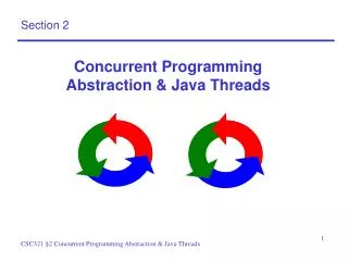
Section 2. Overview. Finite state machine Homework 2 preparation Q&A. Finite State Machine. FSM. Finite automata / State machines Mathematical abstraction Wide application Digital design Communication protocol Language parsing Neural System modeling …. DFA and NFA.


Section 2
E N D
Presentation Transcript
Overview • Finite state machine • Homework 2 preparation • Q&A
FSM • Finite automata / State machines • Mathematical abstraction • Wide application • Digital design • Communication protocol • Language parsing • Neural System modeling • …
DFA and NFA • Deterministic and Non-deterministic • Deterministic means there is only one outcome for each state transition Deterministic Non-deterministic
Design an FSM • We will design a synchronization circuitry that is used in Gigabit Ethernet. Connection running at 1 Gbit/s …..10011001011110011….
FSM example: sync_fsm • FSM that looks for a specific sequence of bits, called comma character. • The Gigabit Ethernet standard specifies a few comma characters, • 0011111001 • 0011111010 • 0011111000 • in this example, we will design for this pattern: 0011111xxx. • The leading zero is the first bit received.
Example Bit Stream • For example, if the incoming bit streams is 00011001110001001110001110011100011100110011100001111100001100111000111000…… • The synchronization circuitry will catch the patterns in red, and flags the output sync bit to 1, (0 for not-in-sync).
Similar to … • Remember when you learn about regular expression? • ab*(c|ε) denotes the set of strings starting with a, then zero or more bs and finally optionally a c: {a, ac, ab, abc, abb, abbc, ...} • The circuit we design operates on 0 or 1 instead of a, b, c…
Elements of FSM • Combinational logic that computes next state • Memory element that remembers the current state • Input and output
State Machine Design Process • 1. Determine the inputs and outputs • sync_fsm • Input: bit_in, 1-bit • Output: comma_detect, 1-bit
State Machine Design Process • 2. Determine the machine states • sync_fsm, 0011111xxx • S0, initial state • S1, received first 0 • S2, received second 0 • S3 ~ S7, received 1s • S8 ~ S10, received either 0 or 1. • In S10, signal comma_detect
State Machine Design Process • 3. Create state/bubble diagram – Mealy or Moore?
State Machine Design Process • 4. State assignment – give each state a particular value. • We have 11 states • Needs at least 4 bits to encode (compact) • One hot encoding (minimize decoding logic) • We use the 4 bit encode.
State Machine Design Process • 5. Create Transition/Output Table
State Machine Design Process • 6. Derive Next State Logic for each state element.
State Machine Design Process • Derive Output Logic • Ouput = S[3] & ~S[2] & S[1] & ~S[0]
State Machine Design Process • 8. Implement in Logisim
Homework 2 preparation • Use tunnel • Demo
8-bit input => 10-bit output • 8-bit input divided into • 3-bit blocks (HGF) • 5-bit blocks (EDCBA) • 10-bit output divided into • 4-bit blocks (fghj) • 6-bit blocks (abcdei)
Running Disparity • The difference between the number of 1s transmitted and the number of 0s transmitted is always limited to ±2, and at the end of each state, it is either +1 or −1. This difference is known as the running disparity (RD). • This scheme only needs two states for running disparity of +1 and −1. It starts at −1.
Difference between RD- and RD+ for an encoding is XOR. • Can minimize to figure out when to XOR and when not.
Split the circuit into smaller components • Cleaner design and easier for testing • 5b/6b encoder, 3b/4b encoder, circuit to figure out more 1 or zero, fsm • Find resource (or ask for help) to understand how the encoding works • Make sure any resource you find is the same as what we have on the appendix (Wikipedia isn’t always right)
Hints • Split the circuit into smaller components • Cleaner design and easier for testing • 5b/6b encoder, 3b/4b encoder, circuit to figure out more 1 or zero, fsm • Find resource (or ask for help) to understand how the encoding works • Make sure any resource you find is the same as what we have on the appendix (Wikipedia isn’t always right)