Light Collection
Light Collection. Once light is produced in a scintillator it must collected, transported, and coupled to some device that can convert it into an electrical signal (PMT, photodiode, …) There are several ways to do this Plastic light guides. Light Guides. Isotropic light emission.

Light Collection
E N D
Presentation Transcript
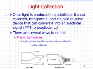
Light Collection • Once light is produced in a scintillator it must collected, transported, and coupled to some device that can convert it into an electrical signal (PMT, photodiode, …) • There are several ways to do this • Plastic light guides
Light Guides Isotropic light emission
Light Guides • Even for total internal reflection over all angles, if Dx1 >> Dx2 there will be substantial light loss
Wavelength Shifters • Liouville’s theorem can be beat by decreasing the energy of the photons • Wavelength shifter can be used • To collect light from large areas and transport it to a small PMT area • To better match the PMT sensitivity • To bend the light path
Wavelength Shifters • Wavelength shifting bars • Wavelength shifting fibers
ATLAS Tile Calorimeter ATLAS Tile Calorimeter
ATLAS Tile Calorimeter ATLAS Tile Calorimeter
ATLAS Tile Calorimeter ATLAS Tile Calorimeter
Outer Reflectors • Usually the scintillator and light guide are wrapped/enclosed with an outer reflector • Measurements at 440 nm,
Photon Detectors • Once light is produced in a scintillator we need to convert it into an electronic signal • Vacuum based (this lecture) • Photomultiplier tubes (PMTs) • Semiconductor (later lectures) • Photodiodes, APDs, SSPM, CCDs, VLPCs, … • Hybrid • Vacuum+semiconductor • Gas based (TEA, TMAE) • For Cerenkov detectors
Photon Detectors • We’ll be interested mainly in the visible region today
Photon Detectors • The main principle used is the photoelectric effect which converts photons into electrons (photoelectrons) • Important quantities characterizing the sensitivity are the quantum efficiency and radiant sensitivity
Windows • Borosilicate typical
Photocathodes • The important process in the photocathode is the photoelectric effect • Photons are absorbed and impart energy to electrons • Electrons diffuse through the material losing energy • Electrons reaching the surface with sufficient energy (> W) escape • Alkalai metals have a low work function • e.g. bialkali is SbKCs
Photocathodes • QE of bialkali PMT’s
Photocathodes • As you can see from the graph, the maximum QE is about 25% for current bialkali • Photoelectron emission is isotropic • 50% to first dynode, 50% to window • Transmission losses • Bialkali photocathodes are ~40% transmissive • 0.5 x 0.4 ~ 0.2
Energy Resolution • In gamma ray spectroscopy and other applications, the energy resolution is an important quantity • One contribution to the energy resolution is the statistical variance of the produced signal quanta • In the case of a PMT, the energy resolution is determined by the number of photoelectrons arriving at the first dynode
Dynode Structure • The dynode structure multiplies the number of electrons • Process is similar to photocathodes but here the incident radiation is electrons
Dynode Structure • There are a variety of dynode structures including some that are position sensitive
Dynode Structure • d of 4-6 for most dynode materials • And typically there are 10-14 stages (dynodes)
Dynode Structure • Typical instantaneous current? • Assume 103 photons at the photocathode • Then there are 2.5x10² electrons at the first dynode • Then there are 2.5x10⁸ electrons at the anode • And collected in 5ns gives a peak current of 2.5x108 x 1.6 x 10-19 / 5 x 10-9 = 8 mA • Of course the average current is much smaller
Dark Current • A small amount of current flows in the PMT even in completely dark state • Causes of dark current include • Thermionic emission from photocathode and dynodes • Leakage current (ohmic leakage) between anode and other electrodes • Photocurrent produced by scintillation from glass or electrode supports • Field emission current • Cosmic rays, radioactivity in glass envelope, radioactivity (gamma) from surroundings (cement) • Dark current increases with increasing supply voltage
PMT Gain and HV Supply • Typical gain versus high voltage curve • Rule of thumb is DV=100 gives DG=2
PMT Base • A voltage divider network is used to supply voltage to the dynodes • Typical supply voltage is 2kV • The manufacturer usually supplies a circuit diagram and often sells the accompanying base
PMT Base • The HV supply must be capable of providing a DC current (to the divider network) as well as average and peak signal currents • Typical signal current ~ 20 mA • Typical average current ~ 20 mA • It is possible that at high rates that the HV supply cannot provide enough current to the last dynodes and hence the PMT voltage will “sag” • Additional charge can be supplied by using capacitors or transistors
PMT Base • Using capacitors or transistors to supply charge
Magnetic Shielding • DV between the dynodes is ~100-200V • Low energy electrons traveling from dynode to dynode can be affected by small magnetic fields (e.g. earth B ~ 0.5 G) • Effect is largest for head-on type PMT’s when the magnetic field is perpendicular to the tube axis • A magnetic shield (e.g. mu-metal) is used to reduce gain changes from magnetic fields
PMT’s • There are a wide range of PMT types and sizes • From Hamamatsu catalog
Light Guides • Liouville’s theorem • Phase space is conserved • Phase space density of photons cannot be increased • You can’t make a tapered light guide without losing light
Light Guides • So for a maximum output angle a2 the input angle a1 is limited • Even for complete TIR, if Dx1 >> Dx2 there will be substantial light loss
Light Guides • Transport light by total internal reflection (TIR) • The air gap between scintillator and wrapping is important • Maximum angle for TIR at light guide output is • For light that does escape the light guide it can be recaptured using specular (Al foil) or diffuse (Tyvek) reflection
Light Guides • An example • Many people use Tyvek but one should do studies for each specific application
Light Guides • There will be some light loss even in the case of equal dimensions
Wavelength Shifter • Liouville’s theorem • Phase space is conserved • Phase space density of photons cannot be increased • You can’t make a tapered light guide without losing light • One can get around Liouville’s theorem by using a wavelength shifter such as BBQ • Light is absorbed and subsequently emitted (isotropically) at a longer wavelength