Download
1 / 35
350 likes | 452 Views
Explore the concepts of addressing and datagram forwarding in internetworking. Learn about IP addressing hierarchy, classes, and notation, as well as the processes of forwarding and routing packets. Discover how ARP and dynamic address resolution work to map IP addresses to physical addresses efficiently.

E N D
CS 164 -- Internetworking Slide Set 8
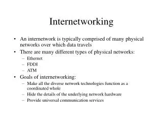
In this set... • Addressing • Datagram forwarding
Requirements for Addressing • Uniqueness -- each host needs to have a unique address. • A global addressing scheme/policy is needed. • Why can we not use underlying Ethernet/MAC layer addresses ? • Unique but there is a “flat” structure -- no hierarchy. • Provides no clues as to how data is to be routed.
IP addressing • IP addressing is hierarchical. IP Address Uniquely identifies network to which host is attached Network Part Host part Identifies host uniquely given the network Note: Hosts on the same physical network can communicate using frames
Addresses and Interfaces • Each host that is attached to the same network has the same “network” part of the IP address. • If routers are attached to multiple networks then, they need to have an address for each network. • Address assigned to the interface on the network. • Appropriate to think of IP addresses as being associated with interfaces.
IP address classes • Hierarchical structure not same for all addresses. • Division into classes, A, B, C, D and E. • D -- multicast, E -- unused. • We are mainly concerned with types A, B and C. • All IP addresses are 32 bits long.
Classes A, B and C • Class A : 7 Network bits, 24 host bits. • Class B: 14 Network bits and 16 host bits. • Class C: 21 Network bits and 8 host bits. • Of approximately 4 billion IP addresses, 1/2 belong to Class A, 1/4 belong to Class B and 1/8 to Class C.
Specifically... • Number of Class A networks = 27 = 128. But on each Class A Network, one can have 224 -2 hosts. • For class C, larger number of networks but each network can have at most 28 = 256 hosts.
IP Address Notation • Dotted Decimal (for IPv4) -- W.X.Y.Z -- each represents each of the four bytes. • Example 171.45.210.4 • Remember -- the source and destination addresses are in the IP header.
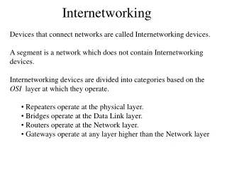
Forwarding versus Routing • Forwarding is the process of taking a packet from the input and sending it on the appropriate output. • Routing -- in contrast -- is the process of building tables that allow the determination of the correct output.
Datagram forwarding A node that gets a datagram first tries to establish whether the destination is on the same physical network. • Compare network part of the destination address with the network part of its own interfaces. • If they are the same, destination is on the same physical network. • If yes, deliver packet. • If no, choose the appropriate router to forward packet. • Next Hop --> router • Consult what is called the forwarding table that contains entries that look like < Network Number, Next Hop>. • Also a default router (possible only default exists).
Our example network • H1 --> H2, same network number in IP address -- deliver via Ethernet. • H1 --> H8. How ? • H1 --> R1 default router over Ethernet. • R1 knows it cannot deliver directly. • R1 has to deliver it to a default router -- R2.
Example Continued • Let us look at R2’s forwarding table. • Thus, R2 --> R3 via PPP and then, finally, R3 --> H8 via Ethernet.
Directly Connected Nets • It is possible to include information with regard to the directly connected networks in forwarding table. • As an example, let PPP interface of R2 be Int 1 and let the FDDI interface be Int 2. Then, the table looks like:
Address Resolution • Physical interface hardware understands only the “link addresses” of the particular network. • Thus, IP addresses have to be translated into a link layer address prior to sending a datagram to a destination or an intermediate router. • Remember Ethernet address == 48 bits -- one way is to encode the host physical address in host part of IP address. • This is however not scalable -- not always possible. • A second way is to maintain a static table that maps an IP address to a physical address -- maintained by our sys admin. The table is copied onto every host.
Dynamic address resolution using ARP • Dynamic resolution is possible using the Address Resolution Protocol or ARP. • Protects against the possibility that Ethernet cards may be replaced. • ARP requires that a dynamic table that maps IP addresses onto physical addresses is refreshed every 15 minutes or so. • It takes advantage of the “broadcast” nature of the link.
ARP Mechanics • When a destination PHY address is to be found, an ARP query is broadcasted. • Query includes destination IP address and link layer address of sending host. • Each host checks for match with indicated IP address. • If match, it sends a response to originator of query with link layer or PHY address. • Originator adds this information into its ARP table. • TTL for each entry in ARP table is 20 minutes. • Just a reminder -- note that a broadcast address consists of all 1s.
0 8 16 31 Hardware type = 1 ProtocolType = 0x0800 HLen = 48 PLen = 32 Operation SourceHardwareAddr (bytes 0 ― 3) ― 5) ― 1) SourceHardwareAddr (bytes 4 SourceProtocolAddr (bytes 0 SourceProtocolAddr (bytes 2 TargetHardwareAddr (bytes 0 ― 3) ― 1) ― 5) TargetHardwareAddr (bytes 2 TargetProtocolAddr (bytes 0 ― 3) ARP Message • Important nuggets : Hardware type specified type of physical network -- Ethernet/FDDI • Protocol Type -- typically IP (higher layer) • Operation -- specified whether query or response.
DHCP • IP addresses not only need to be unique but they need to reflect some structure. • IP address space is limited -- IP addresses cannot be hard configured. • Reconfigurability • In addition to its own address, typically, node needs address of default router. • Manual configuration difficult -- especially in terms of ensuring uniqueness. • Automated configuration is done via DHCP -- Dynamic Host Configuration Protocol.
How does DHCP work ? • DHCP server-- responsible for providing configuration information. • Each host, upon being booted or connected to the network, obtains configuration info. from DHCP. • Note -- admin still picks the IP addresses but now stores them at the DHCP server. • Configuration info stored in a table that is indexed by some unique identifer -- typically the hardware address.
Increasing flexibility • On demand allocation possible with DHCP. • Only a pool of IP addresses specified. • All of these have same network number. • When a host needs an address an unused address from this pool is assigned to the host. • Leasing: When DHCP assigns an address, hosts cannot hold onto address for too long -- lease has to be renewed!
Particulars • To contact the DHCP server, host sends a DHCPDISCOVER message to the broadcast address (255.255.255.255). • DHCP server responds. • Note that a single DHCP server for a plurality of networks (via DHCP relays) • DHCP relay knows DHCP server address. Self Study: DHCP Packet Formats etc.
Error Reporting and ICMP • When a router is unable to process IP datagrams correctly, a collection of error messages sent back to host. • Use of Internet Control Message Protocol or ICMP. • Examples -- host is unreachable, Reassembly process failed, TTL =0, IP header checksum failed etc.
ICMP • Architecturally above IP -- ICMP messages are carried in IP packets and are demultiplexed at receiver. • Examples are ping, traceroute etc. • ICMP-redirect -- ICMP can suggest a better route --default router sends the better route so that host can add new route to its routing table.
Virtual Private Networks • Virtual Private Networks or VPNs: Private networks -- connections among a set of sites. • Private networks have to have their own links but in the shared world ... • One possibility -- Virtual Circuits
IP Tunnels • A virtual point to point link between a pair of nodes that are in fact separated by an arbitrary number of networks. • An IP packet encapsulated within another !
Representing a virtual interface • Router R1 will have a forwarding table that looks like ->
Why IP tunnels ? • Security -- IPSEC -- internal IP packet encrypted. • Specific services -- R1 and R2 may have specific capabilities such as multicast routing. • Other protocols. • Why not ? -- downside is larger IP packets can deteriorate router performance.
Where are we ? • We are done with Section 4.1 • We move onto Section 4.2 -- on Routing.
Routing Tables • Routing is the process by which forwarding tables are built. • A routing table is a precursor to building a forwarding table. • It contains mappings from network numbers to next hops -- which is the next hop for a given network number ? • There may be information as to how this info was got. Can help router decide on when to discard information. • Mainly for calculating changes to topology.
To remind ourselves... • The forwarding table is a mapping between the network number and an outgoing interface. • Can contain some MAC (link layer) info such as the Ethernet address of the next hop.
Network as a graph • We can visualize the network as a graph. • Nodes represent hosts, routers or even networks. • Each edge has an associated cost metric -- how desirable is it to send data on that link ?
The Problem • Find the minimum cost path among any two nodes in the graph. • Cost of the path = Sum of the costs of edges that make up the path. • Process -- Calculate the shortest paths and store in some nonvolatile storage. • We need completely distributed routing policies • centralized approaches not scalable.
Two popular approaches • Routing Information Protocol (RIP) based on Distributed Bellman Ford or Distance Vector Routing • OSPF based on Link State Routing or Dijkstra’s shortest path algorithm.
Next.... • Different routing approaches.