Download
1 / 23
250 likes | 382 Views
This study focuses on the automation of generating patient-specific finite element (FE) models to overcome the limitations in conventional meshing techniques. By utilizing advanced image analysis methods and robust projection techniques, we aim to streamline the development of high-quality hexahedral meshes from medical imaging data. This process is particularly important for guiding surgical procedures involving geometrically complex structures, such as bones in the human body. Our approach demonstrates the potential to improve the applicability of FE analysis in musculoskeletal research.

E N D
Towards Automating Patient-Specific Finite Element Model Development Kiran H. Shivanna1,4, Brian D. Adams2,1, Vincent A. Magnotta3,1,4, Nicole M. Grosland1,2,4 1Department of Biomedical Engineering, 2Department of Orthopaedics and Rehabilitation, 3Department of Radiology, 4Center for Computer-Aided Design The University of Iowa, Iowa City, IA
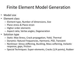
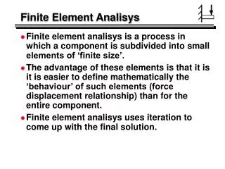
Finite Element Method • Invaluable tool in musculoskeletal research • Demands associated with modeling the geometrically complex structures of the human body often limit its utility – restricting analyses to baseline models • Conventional meshing techniques often prove inadequate
Patient Specific Models • In order to bring FE to the “bedside” for guiding surgical procedures the technique must be unencumbered from the image segmentation and mesh generation process • Overcome the limitations associated with individualized, or patient-specific models
FE Model Development Acquire Medical Imaging Data Surface Generation Generate FE Mesh Segment Regions of Interest Apply Boundary/Load Conditions and Material Properties Finite Element Analysis
Tetrahedral Meshes • Most commonly used solid meshing technique • Several automated techniques for filling a surface based definition of a region of interest • Paving, advancing front, others • Advantages: well developed algorithms, straight forward to implement • Disadvantages: overly stiff elements
Voxel Based Meshing Techniques • Direct conversion of CT data to hexahedral elements • Keyak et al. 1990 • Advantages: easy to implement, voxel-wise material properties, fast • Disadvantages: stair step artifacts in mesh, not appropriate for contact analysis
Hexahedral Meshes • Most commonly used meshing technique for surface contact analysis • Few methods to generate the meshes • Shelling, whisker weaving, mapped mesh • Advantages: More appropriate for surface contact analysis • Disadvantages: Less well developed algorithms, prone to element shape problems, regional control of mesh density difficult
Objective • Automate the generation of high quality hexahedral meshes • Projection method
Bones of Interest Why initiate with the bones of the hand? • Long bones and cuboidal bones • Number of bones per cadaveric specimen • Readily extended to the other long bones of the body
Bones of Interest Extend to irregular bones such as the vertebrae
Image Analysis • Cadaveric specimens were imaged with CT scans • Hand: Cadaveric specimen amputated above the elbow • Spine: Visible male dataset
Projection Method Carpal Bone Bounding Box with Assigned Mesh Seeding Initial Bounding Box Projected Mesh
Extending Projection Method • A single bounding box coupled with the projection technique may not always prove sufficient • Method has been extended to add multiple boxes and/or subdivide existing boxes
Solid Mesh Smoothing • Projection of initial mesh onto the surface oftentimes yields distorted elements • Need to smooth resulting mesh – Iterative Laplacian smoothing for solid mesh • Method • Apply Laplacian smoothing to surface nodes holding interior nodes fixed • Project nodes back onto the original surface • Smooth interior nodes with surface nodes held fixed • Iterate for specified number of iterations or until convergence threshold is reached
Results of Mesh Smoothing Unsmoothed Smoothed Unsmoothed Smoothed
Acknowledgements • Grant funding • R21 (EB001501) • R01 (EB005973) • Nicole Kallemeyn, Nicole DeVries, Esther Gassman