Download
1 / 1
10 likes | 271 Views
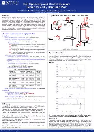
Self-Optimizing and Control Structure Design for a CO 2 Capturing Plant Mehdi Panahi, Mehdi Karimi, Sigurd Skogestad, Magne Hillestad, Hallvard F. Svendsen Norwegian University of Science and Technology. Summary

E N D
Self-Optimizing and Control Structure Design for a CO2 Capturing Plant Mehdi Panahi, Mehdi Karimi, Sigurd Skogestad, Magne Hillestad, Hallvard F. Svendsen Norwegian University of Science and Technology Summary Control plant with the aim of staying close to the optimal operating conditions is objective of this work. Cost function is the energy demand of the plant. It is important to identify good controlled variables (CVs) and the first step is to find the active constraints, which should be controlled to operate the plant optimally. Next, for the remaining unconstrained variables, we look for self-optimizing variables which are controlled variables that indirectly give close-to-optimal operation when held at constant setpoints, in spite of changes in the disturbances. For the absorption/stripping process, a good self-optimizing variable was found to be a temperature close to the top (tray no.4) of the stripper. To validate the proposed structure, dynamic simulation was done and performance of the control structure was tested. CO2 capturing plant with proposed control structure Figure 1. Proposed control structure • General control structure design procedure • I Top Down Step 1: Identify degrees of freedom (MVs): 9 DOFs (5 at steady-state) Step 2: Define operational objectives (optimal operation) • Cost function J (to be minimized): • Operational constraints: CV1: Environmental requirement: Capture 90% of CO2 (active constraint in this case) CV2: Temperature of lean solution to the absorber is 51°C (to get a good operation of the absorber). CV3: Because of the MEA degradation problem, pressure should be less than 2 bar. Stripper top pressure is therefore kept at 1.8 bar CV4: The stripper condenser temperature should be as low as possible and is here assumed to be at 30°C Step 3: Select primary controlled variables (CVs) • Identification of important disturbances: Flue gas flowrate, flue gas composition, stripper pressure • Steady state optimization (nominally and with disturbances) to identify active constraints • Control active constraints (4 equality constraints ) • Candidate CVs for unconstrained DOFs (1 unconstrained DOF) • Trays temperature in the stripper • CO2 composition in the bottom of the stripper • Evaluation of loss for different candidate CVs Table 1- Scaled gain for different candidate CVs Step 4: Where set the production rate (Inventory control)? At feed flue gas flowrate • II Bottom Up Step 5: Regulatory / stabilizing control (PID layer) • What more to control? 4 levels (CV6, CV7, CV8 and CV9) • Pairing of inputs and outputs (see figure 1) Step 6: Supervisory control (MPC layer), Not used here but it can be useful when some MVs reach to constraints Step 7: Real-time optimization, Not needed here (close to self-optimizing) Dynamic Simulation All control loops were implemented and tuned individually using the SIMC method. The final control structure with 9 feedback loops is shown in Fig.1 for the proposed case where the CV is stripper tray temperature no.4. The paring of the loops is quite obvious in this case and is based on minimizing the effective time delay from inputs to outputs. The reboiler duty is used as the MV to control tray temperature no. 4. Results (a) (b) (c) Fig. 3- Objective function in presence of disturbances 1) d1:+5% change from base case, 2) d1:-10%, 3) back to base case 4) d2:+5% change from base case 5) back to base case, 6) d3:+10 kPa, 7) back to base case. Arrows indicate cases with large steady-state losses. Conclusion A self-optimizing concept control structure was designed for a post-combustion CO2 capturing plant. The losses are small which means that it is not necessary to re-optimize the process when different disturbances occur. The plant has 9 dynamic degrees of freedom; 4 of them were used to control equality constraints and 4 of them were used for level control. We found the temperature close to the top (tray no. 4) of the stripper to be a good CV for the remaining unconstrained degree of freedom. r References Grainger, D ., M-B. Hägg, 2008, Techno-economic evaluation of a PVAm CO2-selective membrane in an IGCC power plant with CO2 capture. Fuel, 87, 1, 14-24 Jassim, M. S., G. T. Rochelle, 2006, Innovative Absorber/Desorber Configurations for CO2 Capture by Aqueous Monoethanolamine, Ind. Eng. Chem. Res., 45, 2465-2472 Jensen, J. B., S. Skogestad, 2008, Optimal Operation of Refrigeration Cycles, PhD thesis Skogestad, S., 2004, Control Structure Design for Complete Chemical Plants, Computers and Chemical Engineering, 28, 219-234 Skogestad, S., 2000, Plantwide control: The search for the self-optimizing control structure, Process Control, 10, 487-507 Skogestad, S., I. Postlethwaite, 2005, Multivariable Feedback Control Analysis and Design, 2nd edition Skogestad, S., 2003, Simple analytic rules for model reduction and PID controller tuning, Process Control, 13, 291-309 The 2nd Annual Gas Processing Symposium Qatar, 11-14 Jan. 2010