Light, Reflection, and Refraction
Light, Reflection, and Refraction. Chapters 14 and 15 OPTICS. c. c is the speed of light = 3.00 x 10 8 m/s this is the value for light in space or our atmosphere. speed = (wavelength) x (frequency) c = ƒ. Example. AM Radio waves 7.4 x 10 5 Hz = ?. Energy. E = ħf


Light, Reflection, and Refraction
E N D
Presentation Transcript
Light, Reflection, and Refraction Chapters 14 and 15 OPTICS
c • c is the speed of light = 3.00 x 10⁸m/s this is the value for light in space or our atmosphere. • speed = (wavelength) x (frequency) • c = ƒ
Example • AM Radio waves • 7.4 x 10⁵ Hz = ?
Energy • E = ħf • E is energy • ħ is Planks constant, depending on units it can either be 6.626x10⁻³⁴ Js (Joules seconds) or 4.14×10⁻¹⁵ eVs (electronvolt seconds) • f is frequency
Electromagnetic Waves • Magnetic field wave perpendicular to an electric field wave • All objects emit EMWs. • Temp EMW • Electromagnetic spectrum • Range of all frequencies of light • Visible light is a very small portion of that entire spectrum.
Light path • Light waves travel in straight paths • Change in substance changes direction • Opaque - does not permit light • some light reflected • some light absorbed as heat • Translucent- does permit some light • Transparent- all light goes through
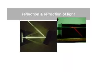
Reflection • Texture affects reflection • Diffuse reflection (rough) • reflects light in many different directions, • Specular reflection (smooth) • reflects light in only one direction • Smooth – variations in surface
Specular and Diffuse Reflection Diffuse Specular
Refraction • Substances that are transparent or translucent allow light to pass through them. • Changes direction of light, bends the light • Due to the differences in speed of light
Analogy • A good analogy for refracting light is a lawnmower traveling from the sidewalk onto mud
Refraction Details, cont. Light may refract into a material where its speed is higher The angle of refraction is greater than the angle of incidence The ray bends away from the normal
Index of Refraction (n) • The ratio of the speed of light in a vacuum to the speed of light in a medium • n - c
Following the Reflected and Refracted Rays Ray is the incident ray Ray is the reflected ray Ray is refracted into the lucite Ray is internally reflected in the lucite Ray is refracted as it enters the air from the lucite
Index of refraction The index of refraction defines the velocity of light in the optically denser medium v=c/n. Speed of light in vacuum (air) Index of refraction Speed of light in a medium (e.g. water)
Index of Refraction, cont. For a vacuum, n = 1 For any other media, n > 1 n is a unitless ratio
Substance Refractive index Air 1.00029 Water 1.33 Ethyl alcohol 1.36 Fused quartz 1.46 Glycerine 1.47 Glass 1.45-1.70 Oil 1.50 Zircon 1.92 Diamond 2.42 Some indices of refraction for various substances at 590 nm:
Frequency Between Media As light travels from one medium to another, its frequency does not change Both the wave speed and the wavelength do change The wavefronts do not pile up, nor are created or destroyed at the boundary, so ƒ must stay the same
Snell’s Law • n1(sin1) = n2(sin2) • To solve for an angle, take inverse sine • r = sin-1{(n1/ n2)(sin1)} • Example • 1 = 30.0⁰ • n1 = 1.00 • n2 = 1.52
i = 30.0⁰ n1 = 1.00 n2 = 1.52 r = ? Sometimes they have i Instead of 1 and r instead of 2!
Total Internal Reflection • If the angle of incidence of a ray is greater than a certain critical angle the ray will reflect rather than refract- it won’t escape the medium! • This principal is responsible for the properties of fiber optic cables.
Critical Angle • sin Θc = n2 / n1 • When solving, Θc=sin-1 (n2/ n1) • What is the critical angle for light traveling from Diamond to Air? ndiamond= 2.42, nair =1.00
Open class set textbooks to page 528 • There’s some good pictures in there, so let’s take a peek! • (The book will use p and q, we will use si and so!)
Mirrors • Light striking a mirror reflects at the same angle that it struck the mirror. Angle in equals angle out.
Flat Mirrors • si = so • si: objects distance to the mirror • so : distance from the mirror to the image • f : focal point • All flat mirrors create a virtual image • Does not exist • Made by our eyes • Behind mirror- that means virtual!
Your image You p q
Ray Diagrams • Used to predict the location of the image of an object. Usually shown as red lines. q p
Concave Spherical Mirrors • Reflective surface is on the interior of a curved surface • C – center of curvature = 2f • R – Radius (distance to C) • f – Focal Point (1/2 R)-or- commonly written as f=R/2. See this in the picture at top of page 531. • Principal axis • any line that passes through C (point where R goes out to) and the middle of the mirror
Mirror Equations • 1/object distance + 1/image distance = 1/focal length 1/si + 1/s0 = 1/f • Magnification (M) Image height/object height or M= - (si / so) -Image distance/Object distance • M = (hi/ ho)= - (si / so)
Sign of Magnification Use UV and IR to remember these! (ultraviolet and infrared)
Rules for Ray Diagraming forConcave Spherical Mirror • A ray traveling through C will reflect back through C • A ray traveling through (f) will reflect parallel to the PA • A ray traveling to the intersection of the PA and the mirror will reflect at the same angle below the PA. • A ray traveling parallel to PA will reflect through the focal point
Ray Diagrams • Draw three rays • The image forms at the point of intersection • Example f = 10.0cm si= 30.0cm ho = 3.00cm *See pictures on page 534!!!!!!!!!!!!
Convex Spherical Mirrors • Reflective surface is on the outside of the curve. • The points f and C are located behind the mirror! • Check out page 537!!!!!!!!!
Rules • A ray parallel to the PA will reflect directly away from f. • A ray towards f will reflect parallel to the PA • A ray to the intersection of PA and mirror will reflect at the same angle below the OA. • Trace the 3 diverging lines back through the mirror to reveal the location of the image which is always virtual
Example • f = -8.00cm • p= 10.0cm • h = 3cm
Parabolic Mirrors • Rays that hit spherical mirrors far away from the OA often reflect though other points causing fuzzy images, spherical aberration. • Telescopes use parabolic mirrors as they ALWAYS focus the rays to a single point.
Thin Lenses • Converging • Diverging • f- curve of lens & index of refraction
Converging Lens Diagram • Ray parallel to PA, refracts through far focal point • Ray through center of lens, continues straight line • Ray through near focal point, refracts through lens, continues parallel to PA • Treat lens as though it were a flat plane.
Diverging Lens Diagram • Because the rays that enter a diverging lens do not intersect a virtual image is formed by tracing back the refracted rays. • Ray 1 - parallel to PA, refracts away from near f, trace back to near f. • Ray 2 - ray toward far f, refracts parallel to PA, trace back parallel to PA • Ray 3 - ray through center, continues straight, trace back toward object