Download

1 / 27
280 likes | 414 Views
Chapter 8 Serial and Parallel Port Interfacing. Valvano’s Intro. To Embedded Systems. 8.1 General Intro. To Interfacing. Three Components Mechanical Design of the Physical Components (Selection of the parts.) Analog and Digital electronics used to connect the physical devices.

E N D
Chapter 8 Serial and Parallel Port Interfacing Valvano’s Intro. To Embedded Systems
8.1 General Intro. To Interfacing • Three Components • Mechanical Design of the Physical Components (Selection of the parts.) • Analog and Digital electronics used to connect the physical devices. • Low-Level Software (transforms the mechanical and electrical devices into objects that perform the desired tasks.
9S12 Interfacing • 9s12 is built using CMOS • Involves consideration of voltage, current, and capacitance.
Digital Output • IOH—largest current a port pin can source when the output is high. • VOH—smallest voltage a port pin can be if the output is high. • VDD—the power into the microcontroller • Output High Voltage is between VDD and VOH.
Digital Output (cont.) • IOL—the largest current a port pin can sink when the output is low. • VOL—the largest voltage a port pin can be if the output is low and the current is less than IOL (the output low voltage will be between 0 and VOL.
Digital Inputs • IIH – the current the input will require when the input is high. • VIH—the voltage above which the input is considered high. • IIL—the current the input will require when the input is low. • VIL – voltage below which the input will be considered low.
Capacitance • Capacitance loading occurs with each input and with long cables. • Input— C=6pF • Time constant CxR where R is the resistance in the interface circuit. • Example: V(t) = 5 – 5 exp(-t/RC) • Output of one circuit is attached to the input of another. • If output goes from 0 to +5volts, the voltage is perceived as V(t)
Device Driver • A collection of software functions that allow higher level software to utilize an I/O device. • Glossary definition( page 517): A collection of software routines that perform I/O functions.
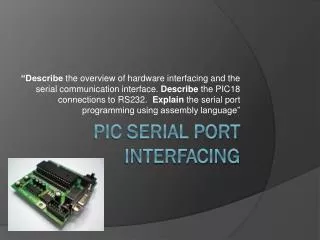
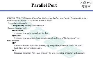
8.2 Serial Communications Interface, SCI • Protocol is same as a UART. • Old, but still in use on modern microcontrollers. • 8.2.1 discusses the RS232 Protocol. • 8.2.2 discusses the transmission of an asynchronous character. • 8.2.3 discusses the reception of an asynchronous character.
8.2.4 9S12 SCI Details • The C32 has one SCI port and the DP512 has two ports. • SCIDRL—SCI Data Register Low byte • Transmit Data Register (Figure 8.3) • Receive Data Register ( Figure 8.4) • SCIBD—(SCI0BD,SCI1BD)—baud rate register.
SCI Baud Rate • SCI Baud Rate Control Register • M—mode bit selects 8-bit (0) or 9-bit(1) data frames. • A frame always has a start bit and 1 or 2 stop bits. • Baud rate—total number of bits/second • SCI Baud Rate= Mclk/16*BR • BR is in bits 12:0 of the SCIBD • Mclk is the module clock—typically the same as E clock.
Table 8.4 (pg.290) • SCICR2 • TE(bit 3) --transmit enable. • RE(bit 2) –receive enable. • TIE(bit 7) –transmit interrupt enable. • TCIE(bit 6) – transmit complete interrupt enable. • RIE(bit 5)—receiver interrupt enable. • ILIE (bit 4)—idle line interrupt enable • RWU(bit 1)—recever wakeup control bit. • SBK(bit 0)– send break bit
Table 8.4 (cont.) • SCICR1 • Loops (bit 7) –enables loop mode. • RSRC (bit 5)—receiver source (when loops=1) • M (bit 4)—mode bit. • WAKE (bit 3)-wake on idle line or msb • ILT (bit 2) – idle line type (for the receiver) • PE (bit 1)– parity enable. • PT (bit 0)—parity type (0 for even parity)
Table 8.4 • SCISR1—SCI status register 1. • TDRE—(bit 7) –transmit data register empty. • TC—(bit 6)—transmit complete flag. • RDRF—(bit 5)—Receive Data Register Full • IDLE—(bit 4)—idle line detected • OR—(bit 3)—overrun error • NF—(bit 2) –noise flag (set if 3 samples are not the same for a received bit.) • FE—(bit 1)—frame error (set when no stop bit is detected.) • PF—(bit 0)—parity flag; (set when parity violation is found and PE bit is set.)
Table 8.4 • SCISR2—SCI status register 2 • Contains two mode control bits and one status bit. • BRK13 (Bit 2)—Break Transmit Character Length • TXDIR (Bit 1)—Transmitter Pin Data Direction • RAF (BIT 0)—Receiver Active Flag
Busy-Waiting • Same as gadfly or polling. • Software continuously checks the hardware status, waiting for it to be ready. • Figure 8.6(page 293)—Flow Charts.
8.3 Serial (Synchronous) Peripheral Interface • Faster than SCI for interconnecting boards and a PC.
8.3.1 SPI Fundamentals • SPI used to attach additional I/O devices (such as A/D’s and D/AC’s). • SPI implements a synchronous protocol. • Same clock is used.
8.3.1 SPI (cont.) • Freescale SPI—4 I/O lines • Slave Select --NOT–optional negative logic control signal. • SClk—50% duty cycle clock generated by the master. • MISO—master in, slave out data line. • MOSI—master out, slave in data line.
SPI (cont.) • Transmitting device uses one edge of the clock for changing data, and the receiving device uses the other edge. • Controlled by CPOL(BIT 3) and CPHA(BIT 2) of the SPICR1 • See Figures 8.7 and 8.8 on page 295. • Pages 296-298 has more details.
8.3.4 8-bit DAC Interface • Example 8.2 Design an 8-bit DAC with range of 0 to +5.
8.4 Scanned Keyboards • Switches are placed in a row/column matrix. • Fig. 8.12 (pg. 301) illustrates a matrix keyboard. • Computer drives one row at a time. • Columns are read to determine which key is pressed.
8.5 Parallel Port LCD Interface with the HD44780 Controller • The HD44780 Controller is an industry standard for interfacing to a Liquid Crystal Display. • ASCII characters can be written to the HD44780 controller. • The ASCII character will be mapped onto the display as a 5 by 8 bit pixel image.
8.6 Binary Actuators • Relays, solenoids, and DC motors have electrical interfaces that are similar.
8.7 Pulse-Width Modulation • PWM can be used to deliver power in a variable manner. • The Duty Cycle can vary • Duty = (H)/(H+L) (the fraction of the time that the signal is high. • Where H is the time that the signal is high. • And L is the time that the signal is low. • Figure 8.21 illustrates the wave forms.
8.8 Stepper Motors • Evaluation of a motor: • Maximum speed (RPM) • Torque • Efficiency of translating electrical power into mechanical power
Stepper Motors (cont.) • Stepper Motors—control the rotational position. • Used in applications where precise positioning is more important than speed, torque, or efficiency.