Download
1 / 19
190 likes | 298 Views
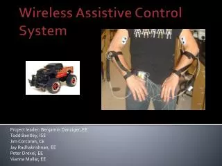
Design and test an EMG-based control system for an RC vehicle, allowing users to control it wirelessly.

E N D
Project leader: Benjamin Danziger, EE Todd Bentley, ISE Jim Corcoran, CE Jay Radhakrishnan, EE Peter Drexel, EE ViannaMullar, EE Wireless Assistive Control System
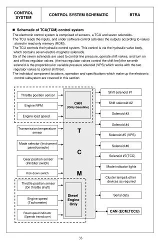
Project Criteria • Mission: Prove a control system can model bio-signals • Goal: Design an interactive proof of concept that prospective students can use at open houses • Purpose: show off the Biomedical Engineering Option Must be safe and robust! • Commissioned by the Electrical Engineering Department
Project Overview • RC Vehicle controlled by Electromyographic (EMG) signals • Convert surface EMG signals from human muscle to computer commands • Send commands wirelessly to an RC Vehicle
Customer Requirements • Strap • Eliminate movement artifact/transients/noise • Simplify electrode application • Signal Processing • Properly distinguish between the muscle groups • Robust Control Algorithm • Wireless Output • RC Vehicle • Bio-signals must control the vehicle's movements • Visual and Audible feedback
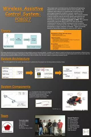
System Architecture Right Bicep Left Bicep BioRadio 150 TX BioRadio 150 RX USB Filter Right Thenar Control System Left Thenar RF Transmitter Lights DC Motor (Forwards/Backwards) MicroProcessor RF Receiver DC Motor (Left Right) Audio
Design Summary: Front End • Strap Design • Originally wanted glove-like design • Infeasible – 25 dimensions on human hand and arm • Anthropometric Design • Adjustable from 5th thru 95th percentile body types. • Expedites application of EMG sensors. • Nylon material construction • Incredibly durable • Nylon tubing hides wires and prevents movements
Design Summary: Front End • EMGs • Non-invasive, uses surface electrodes • Institute Review Board (IRB) • Need approval for human testing • Use of BioRadio • Collects up to 8 bio-signal channels (we’re using 4) • Safely collects all data • Transmits the data wirelessly
Data Acquisition Testing • Acquired data from 5 males and 5 females • Recorded Body Mass Index (BMI) • Tested Normal Weight, Overweight and Obese • Asked if they went to the gym • Ensured action could be performed and recorded by BioRadio150 on all individuals • Observe Crosstalk • Tested strap • Confirmed EMG frequency range • Fatigue Factor Muscle A Muscle B
Design Summary: Signal Processing Custom Moving Average Filter Normalization (Finds max value) Difference (Forward-Reverse) (Right-Left) Level Coding All on or All off • Customer Requirements met: • Channels distinguished • EMG based algorithm • Wireless output Data Packet
Design Summary: RC Vehicle • Receives commands by an RF Receiver • Powered by 6 NiMH AA batteries • Uses a ATtiny2313 Microprocessor • Uses two DC motors (one for turning, one for acceleration), each with its own H-bridge • Visual Feedback: Uses LED system • Audible Feedback: ChipCorder IC is used to play different sound effects correlating to the user’s actions
Design Summary: RC Vehicle Light Scheme on RC Car
Full System Testing • Live System Tests • Used all members of the team and several IRB participants • Ensured all 4 commands were functional • Drove car around the Wetlab
Budget • Final expenditure is $411.32 • Initial cost was $339.59 • Does not include the BioRadio • Budget~ $1000
Difficulties and Future Improvements • Future Improvements: • Electrode Pairs • Implement DSP • Use servo instead of DC motor • RC Vehicle with sharper turning radius • Difficulties: • Obtaining a clean signal • Parallel processing in “Real time”
Final Summary • Meets all Customer Requirements • Within budget • Cost= $411.32 • Budget~ $1000 • We will let YOU determine if it’s a success.
Questions? Do YOU have any Questions?