Understanding Pipelining and Hazards in Advanced Computer Architecture
540 likes | 646 Views
This chapter explores the principles of pipelining in advanced computer architecture, focusing on how instruction execution can be divided into multiple stages such as Instruction Fetch (IF), Instruction Decode (ID), Execute (EX), Memory Access (MEM), and Write Back (WB). It discusses the key features of the DLX architecture, the execution of instructions, and how pipelining can enable concurrent processing, improving performance. The text outlines the different cycles in a multiple-cycle DLX design and presents methods to calculate cycles per instruction (CPI) to measure efficiency gains.

Understanding Pipelining and Hazards in Advanced Computer Architecture
E N D
Presentation Transcript
Chapter 5Pipelining and Hazards Advanced Computer Architecture COE 501
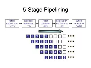
Computer Pipelines • Computers execute billions of instructions, so instruction throughout is what matters • Divide instruction execution up into several pipeline stages. For example IF ID EX MEM WB • Simultaneously have different instructions in different pipeline stages • The length of the longest pipeline stage determines the cycle time • DLX desirable pipeline features: • all instructions same length • registers located in same place in instruction format • memory operands only in loads or stores
DLX Instruction Formats Register-Register (R-type) ADD R1, R2, R3 6 5 11 10 31 26 25 21 20 16 15 0 Op rs1 rs2 rd func Register-Immediate (I-type) SUB R1, R2, #3 31 26 25 21 20 16 15 0 immediate Op rs1 rd Jump / Call (J-type) JUMP end 31 26 25 0 offset added to PC Op (jump, jump and link, trap and return from exception)
Multiple-Cycle DLX: Cycles 1 and 2 • Most DLX instruction can be implemented in 5 clock cycles • The first two clock cycles are the same for every instruction. 1. Instruction fectch cycle (IF) load instruction update program counter 2. Instruction decode / register fetch cycle (ID) fetch source registers sign-extend immediate field
Adder 4 PC Inst ALU 5 Steps of DLX DatapathFigure 3.1, Page 130 Instruction Fetch Instr. Decode Reg. Fetch Execute Addr. Calc Memory Access Write Back Next PC MUX Next SEQ PC Zero? RS1 Reg File MUX RS2 Memory Data Memory L M D RD MUX MUX Sign Extend Imm WB Data
Multiple-Cycle DLX: Cycle 3 • The third cycle is known as the Execution/ effective address cycle (EX) • The actions performed in this cycle depend on the type of operations. • Loads and Stores • calculate effective address • ALU operations • perform ALU operation • Branch • compute branch target • determine if the branch is taken
Adder 4 PC Inst ALU 5 Steps of DLX DatapathFigure 3.1, Page 130 Instruction Fetch Instr. Decode Reg. Fetch Execute Addr. Calc Memory Access Write Back Next PC MUX Next SEQ PC Zero? RS1 Reg File MUX RS2 Memory Data Memory L M D RD MUX MUX Sign Extend Imm WB Data
Multiple-Cycle DLX: Cycle 4 • The fourth cycle is known as the Memory access / branch completion cycle (MEM) • The only DLX instructions active in this cycle are loads, stores, and branches • Loads • load memory onto processor • Stores • store data into memory • Branch • go to branch target or next instruction • ALU Operations • do nothing
Adder 4 PC Inst ALU 5 Steps of DLX DatapathFigure 3.1, Page 130 Instruction Fetch Instr. Decode Reg. Fetch Execute Addr. Calc Memory Access Write Back Next PC MUX Next SEQ PC Zero? RS1 Reg File MUX RS2 Memory Data Memory L M D RD MUX MUX Sign Extend Imm WB Data
Multiple-Cycle DLX: Cycle 5 • The fifth cycle is known as the Write-back cycle (WB) • During this cycles, results are written to the register file • Loads • write value from memory into register file • ALU Operations • write ALU result into register file • Stores and Branches • do nothing
Adder 4 PC Inst ALU 5 Steps of DLX DatapathFigure 3.1, Page 130 Instruction Fetch Instr. Decode Reg. Fetch Execute Addr. Calc Memory Access Write Back Next PC MUX Next SEQ PC Zero? RS1 Reg File MUX RS2 Memory Data Memory L M D RD MUX MUX Sign Extend Imm WB Data
CPI for the Multiple-Cycle DLX • The multiple-cycle DLX requires 4 cycles for branches and stores and 5 cycles for the other operations. • Assuming 20% of the instructions are branches or loads, this gives a CPI of 0.8*5 + 0.2*4 = 4.80 • We could improve the CPI by allowing ALU operations to complete in 4 cycles. • Assuming 40% of the instructions are ALU operations, this would reduce the CPI to 0.4*5 + 0.6*4 = 4.40
Pipelining DLX • To reduce the CPI, DLX can be implemented using a five stage pipeline. • In this example, it takes 9 cycles execute 5 instructions for a CPI of 1.8.
MEM/WB ID/EX EX/MEM IF/ID Adder 4 PC ALU 5 Steps of DLX DatapathFigure 3.4, Page 134 Instruction Fetch Execute Addr. Calc Memory Access Instr. Decode Reg. Fetch Write Back Next PC MUX Next SEQ PC Next SEQ PC Zero? RS1 Reg File MUX Memory RS2 Data Memory MUX MUX Sign Extend WB Data Imm RD RD RD
Reg Reg Reg Reg Reg Reg Reg Reg Ifetch Ifetch Ifetch Ifetch DMem DMem DMem DMem ALU ALU ALU ALU Cycle 1 Cycle 2 Cycle 3 Cycle 4 Cycle 5 Cycle 6 Cycle 7 Visualizing PipeliningFigure 3.3, Page 133 Time (clock cycles) I n s t r. O r d e r
Pipeline Speedup Example • Assume the multiple cycle DLX has a 10 ns clock cycle, loads take 5 clock cycles and account for 40% of the instructions, and all other instructions take 4 clock cycles. • If pipelining the machine add 1-ns to the clock cycle, how much speedup in instruction execution rate do we get from pipelining. MC Ave Instr. Time = Clock cycle x Average CPI = 10 ns x (0.6 x 4 + 0.4 x 5) = 44 ns PL Ave Instr. Time = 10 + 1 = 11 ns Speedup = 44 / 11 = 4 • This ignores time needed to fill & empty the pipeline and delays due to hazards.
Pipelining Summary • Pipelining overlaps the execution of multiple instructions. • With an ideal pipeline, the CPI is one, and the speedup is equal to the number of stages in the pipeline. • However, several factors prevent us from achieving the ideal speedup, including • Not being able to divide the pipeline evenly • The time needed to empty and flush the pipeline • Overhead needed for pipeling • Structural, data, and control harzards
Its Not That Easy for Computers • Limits to pipelining: Hazards prevent next instruction from executing during its designated clock cycle • Structural hazards: Hardware cannot support this combination of instructions - two instructions need the same resource. • Data hazards: Instruction depends on result of prior instruction still in the pipeline • Control hazards: Pipelining of branches & other instructions that change the PC • Common solution is to stall the pipeline until the hazard is resolved, inserting one or more “bubbles” in the pipeline • To do this, hardware or software must detect that a hazard has occurred.
Speed Up Equations for Pipelining For simple RISC pipeline, CPI = 1:
Structural Hazards • Structural hazards occur when two or more instructions need the same resource. • Common methods for eliminating structural hazards are: • Duplicate resources • Pipeline the resource • Reorder the instructions • It may be too expensive too eliminate a structural hazard, in which case the pipeline should stall. • When the pipeline stalls, no instructions are issued until the hazard has been resolved. • What are some examples of structural hazards?
Reg Reg Reg Reg Reg Reg Reg Reg Reg Reg Ifetch Ifetch Ifetch Ifetch DMem DMem DMem DMem ALU ALU ALU ALU ALU One Memory Port Structural HazardsFigure 3.6, Page 142 Time (clock cycles) Cycle 1 Cycle 2 Cycle 3 Cycle 4 Cycle 5 Cycle 6 Cycle 7 I n s t r. O r d e r Load DMem Instr 1 Instr 2 Instr 3 Ifetch Instr 4
Reg Reg Reg Reg Reg Reg Reg Reg Ifetch Ifetch Ifetch Ifetch DMem DMem DMem ALU ALU ALU ALU Bubble Bubble Bubble Bubble Bubble One Memory Port Structural HazardsFigure 3.7, Page 143 Time (clock cycles) Cycle 1 Cycle 2 Cycle 3 Cycle 4 Cycle 5 Cycle 6 Cycle 7 I n s t r. O r d e r Load DMem Instr 1 Instr 2 Stall Instr 3
Example: One or Two Memory Ports? • Machine A: Dual ported memory (“Harvard Architecture”) • Machine B: Single ported memory, but its pipelined implementation has a 1.05 times faster clock rate • Ideal CPI = 1 for both • Loads are 40% of instructions executed SpeedUpA = Pipeline Depth/(1 + 0) x (clockunpipe/clockpipe) = Pipeline Depth SpeedUpB = Pipeline Depth/(1 + 0.4 x 1) x (clockunpipe/(clockunpipe / 1.05) = (Pipeline Depth/1.4) x 1.05 = 0.75 x Pipeline Depth SpeedUpA / SpeedUpB = Pipeline Depth/(0.75 x Pipeline Depth) = 1.33 • Machine A is 1.33 times faster
Three Generic Data Hazards • Read After Write (RAW)InstrJ tries to read operand before InstrI writes it • Caused by a “Dependence” (in compiler nomenclature). This hazard results from an actual need for communication. I: add r1,r2,r3 J: sub r4,r1,r3
Reg Reg Reg Reg Reg Reg Reg Reg Reg Reg ALU ALU ALU ALU ALU Ifetch Ifetch Ifetch Ifetch Ifetch DMem DMem DMem DMem DMem EX WB MEM IF ID/RF I n s t r. O r d e r add r1,r2,r3 sub r4,r1,r3 and r6,r1,r7 or r8,r1,r9 xor r10,r1,r11 RAW Hazards on R1Figure 3.9, page 147 Time (clock cycles)
I: sub r4,r1,r3 J: add r1,r2,r3 K: mul r6,r1,r7 Three Generic Data Hazards • Write After Read (WAR)InstrJ writes operand before InstrI reads it • Called an “anti-dependence” by compiler writers.This results from reuse of the name “r1”. • Can’t happen in DLX 5 stage pipeline because: • All instructions take 5 stages, and • Reads are always in stage 2, and • Writes are always in stage 5 • WAR hazards can happen if instructions execute out of order or access data late
Reg Reg Reg Reg ALU ALU Ifetch Ifetch DMem DMem EX WB MEM IF ID/RF No WAR Hazards on R1 Time (clock cycles) read I n s t r. O r d e r add r4,r1,r3 write sub r1,r2,r3
I: sub r1,r4,r3 J: add r1,r2,r3 K: mul r6,r1,r7 Three Generic Data Hazards • Write After Write (WAW)InstrJ writes operand before InstrI writes it. • Called an “output dependence” by compiler writersThis also results from the reuse of name “r1”. • Can’t happen in DLX 5 stage pipeline because: • All instructions take 5 stages, and • Writes are always in stage 5 • Will see WAR and WAW in later more complicated pipes
Reg Reg Reg Reg ALU ALU Ifetch Ifetch DMem DMem EX WB MEM IF ID/RF No WAR Hazards on R1 Time (clock cycles) read I n s t r. O r d e r add r1,r4,r3 write sub r1,r2,r3
Data Forwarding • With data forwarding (also called bypassing or short-circuiting), data is transferred back to earlier pipeline stages before it is written into the register file. • Instr i: add r1,r2,r3 (result ready after EX stage) ---------------------- • Instr j: sub r4,r1,r5 (result needed in EX stage) • This either eliminates or reduces the penalty of RAW hazards. • To support data forwarding, additional hardware is required. • Multiplexors to allow data to be transferred back • Control logic for the multiplexors
Reg Reg Reg Reg Reg Reg Reg Reg Reg Reg ALU ALU ALU ALU ALU Ifetch Ifetch Ifetch Ifetch Ifetch DMem DMem DMem DMem DMem I n s t r. O r d e r add r1,r2,r3 sub r4,r1,r3 and r6,r1,r7 or r8,r1,r9 xor r10,r1,r11 Forwarding to Avoid RAW HazardFigure 3.10, Page 149 Time (clock cycles)
ALU HW Change for ForwardingFigure 3.20, Page 161 ID/EX EX/MEM MEM/WR NextPC mux Registers Data Memory mux mux Immediate
Reg Reg Reg Reg Reg Reg Reg Reg ALU Ifetch Ifetch Ifetch Ifetch DMem DMem DMem DMem ALU ALU ALU lwr1, 0(r2) I n s t r. O r d e r sub r4,r1,r6 and r6,r1,r7 or r8,r1,r9 Data Hazard Even with ForwardingFigure 3.12, Page 153 Time (clock cycles)
Reg Reg Reg Ifetch Ifetch Ifetch Ifetch DMem ALU Bubble ALU ALU Reg Reg DMem DMem Bubble Reg Reg Data Hazard Even with ForwardingFigure 3.13, Page 154 Time (clock cycles) I n s t r. O r d e r lwr1, 0(r2) sub r4,r1,r6 and r6,r1,r7 Bubble ALU DMem or r8,r1,r9
Software Scheduling to Avoid Load Hazards Try producing fast code for a = b + c; d = e – f; assuming a, b, c, d ,e, and f in memory. Slow code: LW Rb,b LW Rc,c ADD Ra,Rb,Rc SW a,Ra LW Re,e LW Rf,f SUB Rd,Re,Rf SW d,Rd Fast code: LW Rb,b LW Rc,c LW Re,e ADD Ra,Rb,Rc LW Rf,f SW a,Ra SUB Rd,Re,Rf SW d,Rd
Compiler Avoiding Load Stalls Compilers reduce the number of load stalls, but do not completely eliminate them.
DLX Control Hazards • Control hazards, which occur due to instructions changing the PC, can result in a large performance loss. • A branch is either • Taken: PC <= PC + 4 + Imm • Not Taken: PC <= PC + 4 • The simplest solution is to stall the pipeline as soon as a branch instruction is detected. • Detect the branch in the ID stage • Don’t know if the branch is taken until the EX stage • If the branch is taken, we need to repeat the IF and ID stages • New PC is not changed until the end of the MEM stage, after determining if the branch is taken and the new PC value
MEM/WB ID/EX EX/MEM IF/ID Adder 4 PC 5 Steps of DLX DatapathFigure 3.4, Page 134 Instruction Fetch Execute Addr. Calc Memory Access Instr. Decode Reg. Fetch Write Back Next PC MUX Next SEQ PC Next SEQ PC Zero? RS1 Reg File MUX Memory RS2 Data Memory ALU MUX MUX Sign Extend WB Data Imm RD RD RD
Reg Reg Reg Reg Reg Reg Reg Reg Reg Reg ALU ALU ALU ALU ALU Ifetch Ifetch Ifetch Ifetch Ifetch DMem DMem DMem DMem DMem 10: beq r1,r3,36 14: and r2,r3,r5 18: or r6,r1,r7 22: add r8,r1,r9 36: xor r10,r1,r11 Control Hazard on BranchesThree Stage Stall
Control Hazard on Branches • With our original DLX model, branches have a delay of 3 cycles • The delay for not-taken branches can be reduced to two cycles, since it is not necessary to fetch the instruction again.
Branch Stall Impact • If CPI = 1, 30% branch, Stall 3 cycles => new CPI = 1.9! • Two part solution: • Determine branch taken or not sooner, AND • Compute taken branch address earlier • DLX branch tests if register = 0 or 0 • DLX Solution: • Move Zero test to ID/RF stage • Adder to calculate new PC in ID/RF stage • 1 clock cycle penalty for branch versus 3
Pipelined DLX DatapathFigure 3.22, page 163 Instruction Fetch Instr. Decode Reg. Fetch Execute Addr. Calc. Memory Access Write Back This is the correct 1 cycle latency implementation!
Branch Behavior in Programs • Based on SPEC benchmarks on DLX • Branches occur with a frequency of 14% to 16% in integer programs and 3% to 12% in floating point programs. • About 75% of the branches are forward branches • 60% of forward branches are taken • 80% of backward branches are taken • 67% of all branches are taken • Why are branches (especially backward branches) more likely to be taken than not taken?
Four Branch Hazard Alternatives #1: Stall until branch direction is clear #2: Predict Branch Not Taken • Execute successor instructions in sequence • “Squash” instructions in pipeline if branch actually taken • Advantage of late pipeline state update • 33% DLX branches not taken on average • PC+4 already calculated, so use it to get next instruction #3: Predict Branch Taken • 67% DLX branches taken on average • But haven’t calculated branch target address in DLX • DLX still incurs 1 cycle branch penalty • Other machines: branch target known before outcome
Four Branch Hazard Alternatives #4: Define branch to take place AFTER n following instruction branch instruction sequential successor1 sequential successor2 ........ sequential successorn branch target if taken • In 5 stage pipeline, 1 slot delay allows proper decision and branch target address to be calculated (n=1) • DLX uses this approach, with a single branch delay slot • Superscalar machines with deep pipelines may require additional delay slots to avoid branch penalties Branch delay of length n
Delayed Branch • Where to get instructions to fill branch delay slot? • Before branch instruction: always valuable if found • Branch cannot depend on rescheduled instruction (RI) • From the target address: only valuable when branch taken • Must be O.K. to execute RI if branch is not taken. • From fall through: only valuable when branch not taken • Must be O.K. to execute RI if branch is taken Before Target Fall Through ADD R1, R2, R3 … BEQZ R2, target BEQZ R2, target BEQZ R2,target … … … … … ADD R1, R2, R3 target: … ADD R1, R2, R3 …
Filling delay slots • Compiler effectiveness for single branch delay slot: • Fills about 60% of branch delay slots • About 80% of instructions executed in branch delay slots useful in computation • About 50% (60% x 80%) of slots usefully filled • Canceling branches or nullifying branches • Include a prediction of if the branch is taken or not take • If the prediction is correct, the instruction in the delay slot is executed • If the prediction is incorrect, the instruction in the delay slot is squashed • Allow more slots to be filled from the target address or fall through
Evaluating Branch Alternatives Scheduling Branch CPI speedup v. speedup v. scheme penalty unpipelined stall Slow stall pipeline 3 1.42 3.5 1.0 Fast stall pipeline 1 1.14 4.4 1.26 Predict taken 1 1.14 4.4 1.26 Predict not taken 0.7 1.10 4.5 1.29 Delayed branch 0.5 1.07 4.7 1.34 Assume branch frequency is 14%
Compiler “Static” Prediction ofTaken/Untaken Branches • Two strategies examined • Backward branch predict taken, forward branch not taken • Profile-based prediction: record branch behavior, predict branch based on prior run
Pipelining Complications • Exceptions: Events other than branches or jumps that change the normal flow of instruction execution. • 5 instructions executing in 5 stage pipeline • How to stop the pipeline? • How to restart the pipeline? • Who caused the interrupt? Stage Problem interrupts occurring IF Page fault on instruction fetch; misaligned memory access; memory-protection violation ID Undefined or illegal opcode EX Arithmetic interrupt MEM Page fault on data fetch; misaligned memory access; memory-protection violation