Download
1 / 18
180 likes | 327 Views
Irradiation studies of L1 sensors for DØ 2b. Regina Demina University of Rochester. Outline. Radiation environment and silicon sensor specs Results on prototypes Conclusions. Requirements for silicon sensors. Main challenge for silicon sensors - radiation Depletion voltage ( F )

E N D
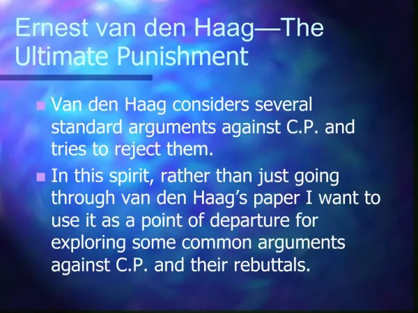
Irradiation studies of L1 sensors for DØ 2b Regina Demina University of Rochester
Outline • Radiation environment and silicon sensor specs • Results on prototypes • Conclusions
Requirements for silicon sensors • Main challenge for silicon sensors - radiation • Depletion voltage (F) • Leakage current (F) noise • Doses comparable to LHC – use their R&D • NB: Uncertainty in F estimate– conservative approach: 1.5 safety margin 10 years of CMS at inner radius
Spec L0, L1 Vbreak>700 V Spec L2-5 Vbreak>350 V Depletion voltage Specification on breakdown voltage derived based on depletion voltage evolution T=-10oC with warm up periods: 4 months 1st year, 1month each next year Hamburg model =20fb-1
Signal to noise ratio • Noise contributions: • Capacitive load: 450+43C(pF) • Al strip resistance + analogue cables (L0) • Shot noise Ileak=I0+aFAd (a=3E-17A/cm) • Thermal noise in Rbias In present design: S/N> 10 T<-10oC for L0 S/N> 18 T<-5oC for L1 Important to test Ileak after irradiation on prototype sensors and on test structures during production Total Ileak=143mA in L0 sensor Corresponds to s/n>10
Irradiation studies at KSU • More details in T. Bolton’s talk • 10 MeV p, sweep the beam using electrostatic deflector • Anneal at 60oC for 80 min, then keep cold • Measure I at 1oC, extrapolate to 20oC Single sided low r sensors with guard band structure produced by HPK
Leakage current • Raw currents measured at T=1oC • Vbreak>700V (spec) =~19fb-1 at r=1.8 cm
I leak vs T • Measure at 1oC, extrapolate to 20oC • Verify temperature dependence
I leak vs F • I= ap Fp • ap=11.610-17 A/cm for 10 MeV p • Hardness of 10MeV protons vs 1 MeV neutrons k= a(10MeVp)/a(1 MeVn)=11.6/4.56=2.54 (compared to3.87*) N.B. a=3.0e-17A/cm for 1 MeV n, if use k=3.87 Extrapolated to @-10oC Ileak=140mA in L0 S/n>10 D. Bechevet et al. NIM A 479(2002)487 At 10 MeV p Montreal * G.P Summers et al., IEEE Trans Nucl. Sci NS-40,6(1993)1372
Depletion voltage vs flux • Use 1/c2 vs V to determine V depl – 30-50% uncertainty
Parameter: C gc ga ka Eaa gy ky Eay Nc0/Neff,0 Value: 1.13E-13 cm-2 1.9E-2 cm-1 1.81E-2 cm-2 2.4E13 s-1 1.09 eV 6.6E-2 cm-1 1.5E15 s-1 1.325 eV 1 - V depl vs F, full size sensors Use Hamburg model with stable damage, short and long term annealing terms Flux in protons/cm2 main effect on C (scales with 1/k)
Other properties after irradiation • Cint: 3 pF(before) 6 pF (after 9.35E13 = 19 fb-1): NC=1680e(before) 1815 (after) S/n>9 No change in R poly after irradiation
Conclusions • Single sided low r sensor technology with guard band structure is used for the inner layers • L1 sensors produced by HPK were tested up to 9.35E13 10 MeV p/cm2 • Hardness factor was found to be 2.54 instead of theoretically predicted 3.87, but in agreement with a study by Rose collaboration • Using this number and 1.5 safety factor we estimate 9.35E13 10 MeV p/cm2 to be equivalent to19 fb-1 at r=1.8 cm (L0) • After this dose • No break down was observed up to 1000 V • Sensors deplete at 350-400 V in agreement with the hamburg model • Based on the observed increase in leakage current we expect Ileak =140 mA for L0 sensors at operating T of –10oC s/n=~10 • Cint increased from 3 to 6 pF, which will lead to increase in C noise from 1680e 1815e • S/n is expected to be above 9 for L0 after 20 fb-1 • We believe that these sensors will perform adequately after 20 fb-1
Fluence estimations for Run IIb • based on CDF silicon leakage current measurements in Run Ia+b • observed radial dependence ~1/r1.7 • measured CDF silicon sensor leakage currents are scaled to DØ sensor geometries and temperatures to give shot noise contributions of leakage currents • for depletion voltage calculations, a 1 MeV equivalent neutron fluence is assumed: • 1Mev n=2.19·1013 r[cm]-1.7 [cm-2/fb-1] (Matthew et al., CDF notes 3408 & 3937) • safety factor 1.5 applied
Performance extrapolations for Run IIb • S/N extrapolations assume • noise in front end of SVX4: 450+43*C(pF) • total silicon strip capacitance: 1.4pF/cm • L0 analog cable assumed (and measured): 0.4pF/cm • noise due to series resistance of metal traces in silicon ~210e-700e depending on module length • noise due to finite value of bias resistor: ~250e • shot noise due to increased leakage currents: • ~1100e for L0 after 15fb-1 if T=-5C • ~1000e for L2 (20cm long module) after 15fb-1 if T=0C
V depl vs F • Test diods