Download
1 / 67
670 likes | 693 Views
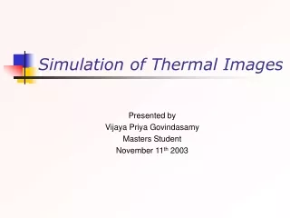
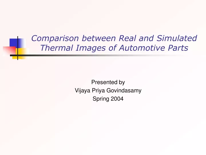
This study presents a comparison between real and simulated thermal images of automotive parts, focusing on thermal image acquisition, simulation, and calibration of thermal imagers. The results and future work are discussed.

E N D
Comparison between Real and Simulated Thermal Images of Automotive Parts Presented by Vijaya Priya Govindasamy Spring 2004
Outline • Thermal Image Acquisition • Simulation of Thermal Images • Calibration of Thermal Imagers • Comparison Between Real and Simulated Thermal Images
Thermal Image Acquisition • Objective • Thermal IR Camera • Process of Acquisition • Indoor Acquisition • Results • Outdoor Acquisition • Results • Points to be considered • Future Work
Objective • The aim of this task is to obtain real thermal images of under vehicle automotive parts • The images obtained will be used to compare with simulated images of the same component under consideration
Indigo Omega Thermal Camera • Camera Specifications • 164 x 128 uncooled microbolometer sensor array • Operating temperature range 0°C to 40°C (-40°C to +55°C ) • Humidity 95% non-condensing • Analog video output NTSC • Remote Interface RS-232 or IEEE 1394 • Dual exposure states • Low temperature range : up to 150°C • High temperature range : up to 500°C Omega Camera and Fire wire Connection
Control Panel • General • Image Optimization • Dynamic Range Control • Flat Field Correction • Video • Video modes • Polarity • Digital • 14-bit data • 8-bit data • Advanced • Spot meter • Isotherm • Camera Temperature • Lens Options
Data Acquisition • In door data collection • Boiling water in a coffee maker and ice cubes were imaged using the camera • The first set of images were taken using the manual mode but the contrast and brightness was changed in between to compensate the camera temperature rise • The second set of images were taken using the fixed mode where the contrast and brightness was fixed • The camera was left on for a some period until the temperature became stable
Results I - Manual Mode Taken for a Period of 35 minutes with a time interval of 5 minutes starting from 0 minute
Color- Coded Thermal Images Taken for a Period of 35 minutes with a time interval of 5 minutes starting from 0 minute
Results II – Fixed Mode Taken for a Period of 35 minutes with a time interval of 5 minutes starting from 0 minute
Color- Coded Thermal Images Taken for a Period of 35 minutes with a time interval of 5 minutes starting from 0 minute
Thermal camera Sony DV camera Data Acquisition contd.. Outdoor Data Collection • The object to be imaged was focused through the thermal camera and the output was recorded as a movie using the Sony DV camera • The engine was started and the imaging process was done for the first ten minutes • The engine was then left running for 15 minutes and the images were again acquired for another 10 minutes • Some under vehicle images have also been acquired Process of acquiring thermal images
Images Acquired – First 10 minutes Pipes connecting muffler and manifolds Engine
Images Acquired – Last 10 minutes Pipes connecting muffler and manifolds Engine
Data Acquisition contd.. • Out Door data collection • The camera was connected to the laptop using the fire wire module • Problems were faced with the driver installation • Finally the data was collected by taking the desktop computer out • Ford Taurus was used to take the images • The images were captured for an hour • Also some color and thermal images were taken. For capturing the thermal images the smart scene option was used
Results - 0 minute and after 10 minutes – Gray scale and color coded
Results - after 20 minutes Intake manifold and Muffler – Gray scale and color coded
Results - after 20 minutes Intake manifold and Exhaust Manifold – Gray scale and color coded
Points to be Considered • Intake manifold just delivers the outside air and fuel mixture • Temperature rise cannot be significantly noted • Parts of interest would be engine block, exhaust manifold or muffler • To obtain a complete thermal image of the entire system the vehicle has to be jacked up
Future Work • Acquire thermal images of the automotive components which show significant change in temperature • Determine the exact time frame of capturing the thermal images with variations • Conduct similar experiments with the Raytheon Infrared Camera
Calibration of Thermal Imagers • Objective • Calibration – Introduction • Calibration Parameters • Calibration Principle • References • Blackbody Calibrators • Review of Blackbody Calibrators
Objective • The idea is to determine the temperature range depicted by each color or gray level value in the thermal image obtained • The first step is to review the literature for the theory and methods of radiometric calibration and then implement a procedure for calibrating the camera • A review of the various blackbody sources is also carried out as a part of this task
Calibration • The process of comparing an instrument's output signal with reality • Radiometric calibration achieves a direct relationship between the gray value response at a pixel and the absolute amount of thermal emission from the corresponding scene element. This relationship is called responsivity. • The gray value response of thermal IR pixels for LWIR cameras is linear with respect to the amount of incident thermal radiation.
“Theory and methods of radiometric calibration” - C. L. Wyatt (SPIE Proceeding 1976) • Instruments must be qualified in four independent domains • Field of view • Spectral Band pass • Time • Polarization • General Objective – obtain an inferential relationship of the remote source in terms of the incident flux and the instrument output - Magnitude of radiant entity R – Complete characterization of all four domains • Revised Objective – the calibration should be conducted under conditions which reproduce, as completely as possible, those conditions under which the measurements are to be made
“Theory and methods of radiometric calibration” - C. L. Wyatt (SPIE Proceeding 1976) • Functional parameters of Calibration • Noise – the extent of error associated with any measurement • Linearity – can be measured as a relationship between source area and instrument output • Spatial response – the goal of measurement of a radiant source, with respect to spatial parameters, is to obtain a measure of the total flux in a small region about the optical axis of the instrument • Temporal response - the measurement goal with respect to time, is to obtain a measurement of the flux at a specific time (or as a function of time) or as a function of position (in time) for moving targets or instruments • Polarization response – obtain a characterization of the polarization of the source, or to ascertain if the measurement is polarization dependent • Spectral response – obtain a measure of the total flux in a specified region about the center wavelength
Calibration Parameters • Spectral response R(λ) • Signal transfer function – A curve that represents input/output relation of the camera • The radiance gain ratio between gain setting G1 and gain setting G2 is defined by • The modulation transfer function – Relates the image quality to its spatial frequency content. • Field of view of the Camera
Calibration Principle • The components for calibration setup include • IR system • Optical path between target and IR system • Target characteristics • Reference blackbodies • The apparent target irradiance Eap is given by • If the target completely fills the IFOV, then F(r) is the system IFOV, Ωs. The target radiance L is given by
Calibration Principle • In the absence of background radiation or target emssivity is unknown, the target area is taken as a blackbody and radiance is given by
Calibration Principle • The gray –scale G(i) ( i= number of the gray level) is related to the detector output V(i) and apparent radiance L(i) by • The apparent radiance LA and LB for the two blackbodies (gray-levels GA and GB) located directly in front of the aperture and set at temperatures TA and TB is
Target Field of view Blackbodies IR Camera Object plane Calibration Principle Blackbody and the target at same range • Select system gain to produce an image without saturation • In the first step, the aperture apparent radiance LA and LB for the two blackbodies, set at temperatures TA and TB are calculated from • Next step is to determine the relation between radiance and gray-level by calculating the coefficients a and Loffusing the gray-levels of the blackbodies, GA and GB, from • The apparent target temperature Tt is found from Lt, where Lt = a Gt + Loff, by inversely solving the integral to obtain L as Relation between radiance, target temperature and radiance
References • A hot calibration load of measuring and controlling temperature – Zhihui Xiao International journal of Infrared and Millimeter Waves, Vol. 21, No. 7, 2000 • Theory and methods of radiometric calibration - C. L. Wyatt (SPIE Proceeding 1976) • Brightness temperature emitted by radiometer calibration load at millimeter wave band – Zhihui Xiao et al., International journal of Infrared and Millimeter Waves, Vol. 22, No. 4, 2001 • T.J. Quinn: Monographs in Physical Measurement: Temperature. Academic Press, New York, USA, 1983. • Irving J. Spiro: Selected Papers on Radiometry, SPIE Milestone Series, Volume MS 14, SPIE – The International Society for Optical Engineering, USA, 1990.
References contd.. • A New Thermal Infrared Camera Calibration Approach using the Wireless MEMS Sensors – Peter Bajcsy, Communication Networks and Distributed Systems Modeling and Simulation Conference(2004) • Calibration of thermal imagers – Paul Chevrette, SPIE, Vol. 661, 1986, pp. 372 – 382 • Spectral and Radiometric Calibration of Midwave and Longwave Infrared cameras – Marc Mermelstein, Optical Engineering(2000), Vol.39, No. 2,pp. 347-352 • J.V. Nicholas, D.R. White: Traceable Temperatures, an Introduction to Temperature Measurement and Calibration, John Wiley & Sons, New York, USA, 1994. • Paul Chevrette: Calibration of Thermal Imagers, Proceedings-of-the-SPIE-The-International-Society-for-Optical-Engineering, Vol. 661, pp. 372-382, 1986.
References contd.. • Radiometric calibration of infrared detectors and thermal imaging systems – Fox, SPIE, Vol. 2474,1995, pp. 229 -237 • Radiometric calibration system for IR cameras - Park, SPIE, Vol. 1686,1992, pp.35 – 41 • Calibrating spectral images using penalized likelihood – G.W.A.M van der Heijden et al., Real –Time imaging Vol. 9, 2003 • Thermal infrared characterization of ground targets and backgrounds - Jacobs, Pieter A. (Book) • T. P. Merritt and F. F. Hall, JR: Blackbody Radiation, Proceedings-of-the-SPIE-The-International-Society-for-Optical-EngineeringProceedings, Vol.47 (2), pp. 1435-1441, 1959
Blackbody Calibrators • Objects that are not at absolute zero radiate energy in the form of electromagnetic waves. • A blackbody absorbs all the radiation it receives and radiates more thermal radiation for all wavelength intervals than any other mass of the same area and temperature • The rate at which a blackbody radiates energy is given by the Stefan-Boltzmann Law: Blackbody Cavities
Blackbody Calibrators • Type of blackbody • High emissivity • Grayness • Entrance aperture diameter • Response time
Future Work • Implement a calibration procedure for the thermal cameras available in IRIS lab • Review more papers for radiometric calibration • Complete the review of Blackbody calibrators and purchase one for the calibration setup to be developed
Simulation of Thermal Images • Objective • Models simulated in Spring 2004 • Simulation of Toyota engine + under vehicle chassis • Simulation of Under vehicle model – one temperature curve assigned • Simulation of Under vehicle model – one temperature curve + fluid temperature assigned • Simulation of Under vehicle model – one temperature curve + advection links assigned • Simulation of Whole Car body without and without environmental conditions
Objective • The objective is to simulate thermal images of automotive parts and compare the results of simulation with real thermal images of the automotive parts under consideration • Need for Simulation • Reduces the time and cost of developing prototypes for test purposes • Gives more flexibility in controlling the parameters • Infrared prediction measurements are accurate and faster
Toyota Chassis + Engine • The Toyota under vehicle model and the Toyota engine model was combined to form a complete model • Some parts like the radiator fan, nameplate were removed from the mesh in order to reduce the mesh volume • The simulation temperature curve was for a period of 15 minutes • Environmental conditions were included based on the weather file (July 19th 1984)
Simulation of Under Vehicle Model • Temperature curve assigned to engine block • The under vehicle model geometry created using Rhino3d was used • Temperature curve was assigned for a period of 15 minutes • All other parts expect engine block was set as calculated temperature part
Simulation of Under Vehicle Model • Temperature curve assigned to engine block and fluid temperature assigned to exhaust components • The temperature curve was assigned to engine block for a period of 15 minutes • The exhaust system components like catalytic converter, muffler and pipes were assigned a fluid temperature of 50 degree Celsius • Drawback – The exhaust components are at high temperature starting from time 0
Fluid parts • The parts have no geometry • The main fluid part requires the assignment of temperature value or curve • The other fluid parts are connected to the corresponding upstream fluid through advection links • The connection requires the flow type and the flow rate
Simulation of Under Vehicle Model • Temperature curve assigned to engine block and fluid parts connected through advection and convection links • The temperature curve was assigned to engine block for a period of 15 minutes • Four fluid parts namely exhaust gas, front pipe exhaust gas, muffler exhaust gas and rear pipe exhaust gas were created • The whole muffler was broken down into three parts – front pipe, muffler, rear pipe
The exhaust gas was assigned the following temperature curve All the fluid parts were connected through advection links The fluid parts and the corresponding solid parts were connected through convection links Simulation of Under Vehicle Model