Download
1 / 30
300 likes | 434 Views
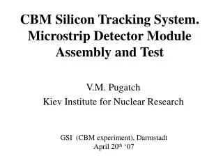
V.M. Pugatch Kiev Institute for Nuclear Research. CBM Silicon Tracking System. R esults of the pre- prototype detector module test. Thanks to coauthors: M. Borysova 1 , J.M. Heuser 2 , O. Kovalchuk 1 , V. Kyva 1 , Lymanets 1,3 , V. Militsiya 1 , O. Okhrimenko 1 , A. Chaus 1 ,

E N D
V.M. Pugatch Kiev Institute for Nuclear Research CBM Silicon Tracking System.Results of the pre-prototype detector module test. • Thanks to coauthors: • M. Borysova 1, J.M. Heuser 2, O. Kovalchuk 1, V. Kyva 1, • Lymanets 1,3, V. Militsiya 1, O. Okhrimenko 1, A. Chaus1, • D. Storozhik1, V. Zhora 4, V. Perevertailo 4, • Galinskiy 5 • 1 KINR, Kiev • 2 GSI, Darmstadt, • 3 now at FIAS, J.W. Goethe University, Frankfurt, • 4 Institute of Microdevices (Kiev) • 5 SPA AEROPLAST (Kiev) V. Pugatch CBM Collaboration Meeting, Dubna, Oct. 13-17 2008
R&D: Agreement ‘KINR-GSI’ • A low-mass mechanical assembly of double-sided silicon microstrip sensors and their connection through analog readout cables to a readout electronics • construction of an experimental test stand • A quality assurance procedure suitable for a future larger detector module production. V. Pugatch CBM Collaboration Meeting, Dubna, Oct. 13-17 2008
Prototype for evaluations:LHCb Silicon Tracker – supporting boxes with cooling pipes Cooling infrastructure and temperature monitoring for the CBM detector module - design at the AEROPLAST (Kiev). Cooling inside of the supporting ladders … Negotiations are in progress wrt involvement into the Detector Module Cooling activity of joint German-Ukrainian venture Labor-Technik LTD www.labor-technik.com.ua V. Pugatch CBM Collaboration Meeting, Dubna, Oct. 13-17 2008
ASSEMBLY of the Module prototype • 1st prototype – the design similar to the long ladders of the LHCb Silicon Tracker – modified for the double-sided version of sensors V. Pugatch CBM Collaboration Meeting, Dubna, Oct. 13-17 2008
Prototype Module assembly scheme Separated heat flow by making different supporting frames: - for hybrids with readout chips - for Si-sensor (to prevent heating of the sensor) V. Pugatch CBM Collaboration Meeting, Dubna, Oct. 13-17 2008
Supporting frame A low mass module- to minimize multiple Coulomb-scattering of charged particles in the detector and support materials. • AEROPLAST(Kiev) – design and production: Three-layer frames composed by two flat plates (0.25 mm thick) with foam layer (1 mm thick, density - 0.7 g/cm3) in between three types to match the sizes of prototype silicon sensors CBM01, CBM01-B1, CBM01-B2 . V. Pugatch CBM Collaboration Meeting, Dubna, Oct. 13-17 2008
Microcables for the discrete electronics readout Side A: Connecting by ultrasonic bonding to sensors 4 Different cables were needed for every type of the sensors: In total, 16 types cables were designed and produced Side B: Connecting by soldering to preamplifiers V. Pugatch CBM Collaboration Meeting, Dubna, Oct. 13-17 2008
Microcables for the discrete electronics readout CBM01-B2-sensor 50,7 μm – pitch Double-sided Sensor is glued to the AEROPLAST Carbon fiber supporting frame Microcables are bonded to sensor pads: Even strips – to one side; odd strips to the opposite side LEMO connectors are soldered by wires to large pads on microcables V. Pugatch CBM Collaboration Meeting, Dubna, Oct. 13-17 2008
Micro-cables suitable for connecting sensors and n-XYTER microchip A double-layer micro cable • 25 µm wide, 20 µm thick Al strips • 101.4 µm pitch • on 24 µm thick polyimide film has been designed and produced at the Institute of Microdevices (IMD, Kiev). Different cables of that type have been tested using them for the CBM01 (50 x 50 mm2 ) sensor readout by a discrete electronics V. Pugatch CBM Collaboration Meeting, Dubna, Oct. 13-17 2008
Cooling infrastructure Thermo-isolating box shielded against r/f pick-up has been designed and built. • Thermo sensors (two types) • Pt-100 • Institute of Microdevices (Kiev) production (based on microcable technology) • were installed to monitor temperature at different areas of the detector module V. Pugatch CBM Collaboration Meeting, Dubna, Oct. 13-17 2008
Cooling infrastructure Cooling studies V. Pugatch CBM Collaboration Meeting, Dubna, Oct. 13-17 2008
Cooling infrastructure Thermo-mechanical tests with dummy silicon samples glued by silicon glue onto the supporting frames: • perfect mechanical rigidity for all supporting frames but one • thermo-conductivity appr. 0.6 W/m*deg in the longitudinal direction • A special design has been developed for investigating cooling by circulating a liquid agent in hollow plates. Currently such structure didn’t show needed mechanical stability. It might be improved at the price of increasing the transversal size of the frame up to 5 mm (keeping material budget still within a required 0.3 X0 ). • Negotiations with joint German-Ukrainian venture Labor-Technik LTD www.labor-technik.com.ua V. Pugatch CBM Collaboration Meeting, Dubna, Oct. 13-17 2008
Sensors characterization • The first detector module prototypes equipped with CBM01B1, CBM01B2 as well as CBM01 sensors have been mounted and connected to a discrete electronics at the readout board. • Tests are performed at KINR using laser pulses (640 nm) and radioactive sources. V. Pugatch CBM Collaboration Meeting, Dubna, Oct. 13-17 2008
Sensors characterization • Mounting sensors on • Supporting AEROPLAST frame • Connecting p-, and n-strips • by microcables to LEMO • connectors – inputs to PA V. Pugatch CBM Collaboration Meeting, Dubna, Oct. 13-17 2008
Measurements with radioactive sources Ra-226, 4 lines – alpha-source. Test setup at KINR: coincident energy spectra for pairs of adjacent strips Charge, Strip ” k” Interstrip gap data strips functionality charge sharing full depletion voltage Charge, Strip “k+1” • Irradiation in two steps: • from p-side (4-lines structure should be clearly pronounced • at any allowed depletion voltage) • 2. from n-side (4-lines structure should appear at full depletion voltage) V. Pugatch CBM Collaboration Meeting, Dubna, Oct. 13-17 2008
Measurements with radioactive sources CBM01-B1-sensor 80 μm – pitch, 226 Ra from p-side, p-strips read-out, HV 0 – 50 V Unexpected performance ! Illustrates problem with electric field in the interstrip gap V. Pugatch CBM Collaboration Meeting, Dubna, Oct. 13-17 2008
Measurements with radioactive sources CBM01-B1-sensor 80 μm - pitch 226 Ra from n-side, HV = 10 V HV = 30 V Approaching full depletion voltage … Yet! There was never clear separation of events belonging to 4 alpha-lines : Thick (10 -15 μm) dead layer from n-side ? Non-depleted sensor, N-strips are shortened (events along the diagonal) V. Pugatch CBM Collaboration Meeting, Dubna, Oct. 13-17 2008
Interstrip gap – charge collection efficiency low ? • Depletion Voltage 0 V 4 V 4 V Single strip spectrum Coincident spectra of adjacent strips V. Pugatch CBM Collaboration Meeting, Dubna, Oct. 13-17 2008
Sr-90 – β-source (selecting its MIP part). MIP – trigger (high energy tail in PM-2) Measuring PM – Si-strip coincidences. Measurements with radioactive sources Sr - 90 РС – interface PC Pentium 1200 MHz PM-1 Si-det. PM-2 Test Setup at KINR Measure Landau MIP peak (for p- as well as n-strips) as a function of depletion voltage: Determine full depletion voltage V. Pugatch CBM Collaboration Meeting, Dubna, Oct. 13-17 2008
Measurements with radioactive sources90Sr – β-source (CBM01-B2 sensor) • p-strip MIP-spectra MIP-spectra have nice Landau-shape at low depletion voltage, while at higher than 30 V the noise makes it gaussian-like one. V. Pugatch CBM Collaboration Meeting, Dubna, Oct. 13-17 2008
Measurements with radioactive sources90Sr – β-source(CBM01-B2 sensor) • n-strip MIP-spectra – non Landau shape – noise from high leakage current smears spectrum V. Pugatch CBM Collaboration Meeting, Dubna, Oct. 13-17 2008
Laser test setup LHCb Laser setup at Zurich University – Measuring in atmosphere V. Pugatch CBM Collaboration Meeting, Dubna, Oct. 13-17 2008
Laser test setup at KINR V. Pugatch CBM Collaboration Meeting, Dubna, Oct. 13-17 2008
Laser test setup CBM01 sensors test results Interstrip gap is irradiated by focused laser beam. Coincident spectra at different depletion voltage from n –side allow determination of full depletion voltage. Notice: linear response exists at very narrow central part of the interstrip gap – -close to 5 μm, only - Necessity to measure precisely η-function – for improving hit position resolution V. Pugatch CBM Collaboration Meeting, Dubna, Oct. 13-17 2008
Laser test setup at KINR 4th year students from Kiev University – Measuring η-function For the CBM-01 sensor V. Pugatch CBM Collaboration Meeting, Dubna, Oct. 13-17 2008
Laser test setup at KINR Laser spot moving from one strip to another one also changing a spot brightness V. Pugatch CBM Collaboration Meeting, Dubna, Oct. 13-17 2008
Laser test setup at KINR Analog signals from adjacent strips – Laser spot appr. at the middle of the interstrip gap V. Pugatch CBM Collaboration Meeting, Dubna, Oct. 13-17 2008
Laser test setup at KINR • Analog signals • From adjacent strips- • Laser spot is close to one of • the strips (large amplitude) • Negative pulse at another • strip – reason unknown • Plan to check • whether this • happens also • for particles V. Pugatch CBM Collaboration Meeting, Dubna, Oct. 13-17 2008
Laser test setup at KINR V. Pugatch CBM Collaboration Meeting, Dubna, Oct. 13-17 2008
Summary. Outlook • Test setup(r/a sources, laser, cooling infrastructure) was designed and built at KINR • Pre-Prototype Detector Modulecomponents (supporting frames, sensors, microcables, cooling) and their connections were tested. • Results: • B1, B2 - sensors -Unexpected performance in the interstrip gap. -Long term instability of the leakage current • Supporting frames perfect features (low mass, mechanical rigidity, thermoconductivity, easy connection and geometry shaping etc.,) • Microcables (including double-layer structure) perfect electrical and mechanical features matching CBM request. • Real modules assembly and their Quality Assurance could be provided by KINR in collaboration with IMD (Kiev), IAP (Sumy) and AEROPLAST (Kiev). V. Pugatch CBM Collaboration Meeting, Dubna, Oct. 13-17 2008