Download
1 / 12
120 likes | 252 Views
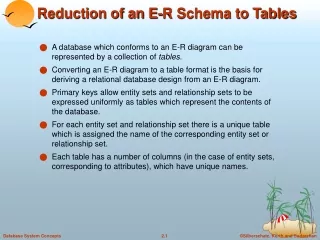
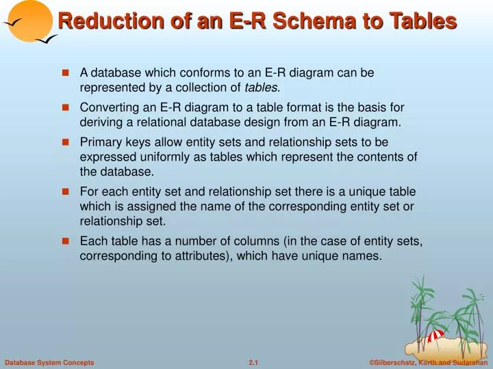
Reduction of an E-R Schema to Tables. A database which conforms to an E-R diagram can be represented by a collection of tables . Converting an E-R diagram to a table format is the basis for deriving a relational database design from an E-R diagram.

E N D
Reduction of an E-R Schema to Tables • A database which conforms to an E-R diagram can be represented by a collection of tables. • Converting an E-R diagram to a table format is the basis for deriving a relational database design from an E-R diagram. • Primary keys allow entity sets and relationship sets to be expressed uniformly as tableswhich represent the contents of the database. • For each entity set and relationship set there is a unique table which is assigned the name of the corresponding entity set or relationship set. • Each table has a number of columns (in the case of entity sets, corresponding to attributes), which have unique names.
Representing Entity Sets as Tables • A strong entity set reduces to a table with the same attributes.
Composite and Multivalued Attributes • Composite attributes are flattened out by creating a separate attribute for each component attribute • E.g. given entity set customer with composite attribute name with component attributes first-name and last-name the table corresponding to the entity set has two attributesname.first-name and name.last-name • A multivalued attribute M of an entity E is represented by a separate table EM • Table EM has attributes corresponding to the primary key of E and an attribute corresponding to multivalued attribute M • E.g. Multivalued attribute dependent-names of employee is represented by a tableemployee-dependent-names( employee-id, dname) • Each value of the multivalued attribute maps to a separate row of the table EM • E.g., an employee entity with primary key John and dependents Johnson and Johndotir maps to two rows: (John, Johnson) and (John, Johndotir)
Representing Weak Entity Sets • A weak entity set becomes a table that includes a column for the primary key of the identifying strong entity set
Representing Relationship Sets as Tables • A many-to-many relationship set is represented as a table with columns for the primary keys of the two participating entity sets, and any descriptive attributes of the relationship set. • E.g.: table for relationship set borrower
Redundancy of Tables • Many-to-one and one-to-many relationship sets that are total on the many-side can be represented by adding an extra attribute to the many side, containing the primary key of the one side • E.g.: Instead of creating a table for relationship account-branch, add an attribute branch to the entity set account
Redundancy of Tables (Cont.) • For one-to-one relationship sets, either side can be chosen to act as the “many” side • That is, extra attribute can be added to either of the tables corresponding to the two entity sets • If participation is partial on the many side, replacing a table by an extra attribute in the relation corresponding to the “many” side could result in null values • The table corresponding to a relationship set linking a weak entity set to its identifying strong entity set is redundant. • E.g. The payment table already contains the information that would appear in the loan-payment table (i.e., the columns loan-number and payment-number).
Representing Specialization as Tables • Method 1: • Form a table for the higher level entity • Form a table for each lower level entity set, include primary key of higher level entity set and local attributes tabletable attributesperson name, street, city customer name, credit-ratingemployee name, salary • Drawback: getting information about, e.g., employee requires accessing two tables
Representing Specialization as Tables (Cont.) • Method 2: • Form a table for each entity set with all local and inherited attributes table table attributesperson name, street, city customer name, street, city, credit-ratingemployee name, street, city, salary • If specialization is total, table for generalized entity (person) not required to store information • Can be defined as a “view” relation containing union of specialization tables • Drawback: street and city may be stored redundantly for persons who are both customers and employees
Relations Corresponding to Aggregation • To represent aggregation, create a table containing • primary key of the aggregated relationship, • the primary key of the associated entity set • any descriptive attributes
Relations Corresponding to Aggregation (Cont.) • E.g. to represent aggregation manages between relationship works-on and entity set manager, create a tablemanages(employee-id, branch-name, title, manager-name) • Table works-on is redundant provided we are willing to store null values for attribute manager-name in table manages