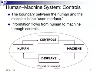
Controls System Installation Status
Controls System Installation Status. Ernest Williams for Controls Department. Outline. LCLS Control System Installation Project Staff and Assignments Schedule & the Process Cable Plant, racks and other infrastructure I&C Systems status and schedule Software Status Issues & Concerns

Controls System Installation Status
E N D
Presentation Transcript
Controls SystemInstallation Status Ernest Williams for Controls Department
Outline • LCLS Control System Installation • Project Staff and Assignments • Schedule & the Process • Cable Plant, racks and other infrastructure • I&C Systems status and schedule • Software Status • Issues & Concerns • Summary
Project Staff • Dedicated LCLS Control System Deputy (E. Carrone) to help drive the project. • E. Williams: Installation Manager. • M. De Salvo: Coordination Manager. • Each subsystem “owned” by a System Lead, responsible for schedule, resources and costs. • Additional support provided by services from PCD. • Cable Shops and Fab Shops. • Controls Coordination Forum: every Thursday at 9.00 am.
Plans & Process for LCLS Controls System Installation • Controls installation takes place in several steps: • Design, documentation, procurement and Installation of the cable plant including long haul DC and I&C cables • Cables termination and connection to beam line components (Mechanical Systems) • Procurement & preparation of electronics racks • Installation of electronics chassis and modules including crates, IOCs, networks & timing modules in the racks • Rack installation in the field, AC & cable plant connection
Cable Plant Design & Installation Process • From the list of devices to be installed… • Develop racks layout & cable tray design • Generate rack profiles for electronics modules • Identify DC & I&C cabling requirements & document in CAPTAR • Produce installation bid package from CAPTAR and tray designs • Generate installation bid package & award contract • Procure trays, cables, connectors, etc. • Install cable plant and terminate to beam line components
The readiness status of each Controls Subsystem is tracked weekly
The readiness status of all controls racks are reviewed weekly (sheet on SharePoint)
Rack Profiles on SharePoint • For each I&C rack we track the equipment to be installed in each “row” • Green – Installed • Yellow – Not installed, but there are no issues • Red – Cause for concern
Controls Installation Schedule Overview LTU/Undulator/e-DumpControls InstallationOverview
Control System Cable Plant & Racks • Nearly 100% of cable plant is installed and terminated. • All Instrumentation Racks are installed and operational
Control System Crates & IOCs, Modules • VME Crates are all installed and operational • All IOCs are installed and operational • We are in the end-to-end checkout phase • There are currently no anticipated major delays in completing most of the pre-beam checkout.
IOCs • Large number of IOCs running reliably for LCLS Accelerator • 136 Coldfire-based embedded IOCs • Mainly used for BPM and LLRF front-end processors • 104 MVME6100 IOCs • 33 MVME3100 IOCs • Beamlines will also use some number RTEMS-based IOCs for Slow controls
Magnet Power Supply Control • Magnet Control System ready to support end-to-end checkout • Alarm Handler, SCORE, ChannelWatcher and Archiver configs are ready
Safety Systems • Separate talks later today on Safety Systems • BCS • Mature design • Project is on schedule • PPS • The Initial Acceptance Test of the Undulator Complex has been executed. • New documentation control process in place
MPS Systems • MPS • Concurrently developing new LCLS MPS • Response time of less than one pulse at 120 Hz • New hardware extended 1.2 km past current MPS • Non-CAMAC • Ready for photon section • Pre-beam checkout will begin mid November
Networks • Accelerator Network Infrastructure supports I&C Ethernet and MPS • The project consists of: • Network architecture design • Cable Plant Davis Bacon Phase IV & Phase V Contracts • Fiber Termination Contract • e-Controls networks Integrate with other networks: • Undulator Alignment Diagnostics System Network • Conventional Facilities • Photon Sections • SLAC Scientific Computing and Computing Services (SCCS) centralized networking groups are helping with all networks • New network tech hired on to support Terri Lahey
Network Design • Accelerator Switches reside in service buildings 911, 912, 913 and 921, and FEE • Undulator accelerator switches are in service buildings B913 & B921 to reduce heat-load • The network consists of Cat6 long hauls between service building patch panels and cat6 boxes at racks • Tunnel walkup stations: one each COW and wireless access • Other IOCs are located in service buildings: MPS, BPM, etc. • Fiber Trunks support Ethernet switches and MPS
Davis Bacon & Fiber Contracts • Phase IV: • install and test cat6 long hauls • Phase V: • fiber pull • Fiber Termination Contract • terminate and test fibers for e-beam, photon, & timing • SCCS/Lahey created contract using knowledge/process learned from BC2 fiber termination contract
Networks Procurements • Fiber trunks purchased • The order for network switches is in purchasing • DIGI terminal servers have been ordered • Patch panels have been ordered • Remaining: fiber jumpers and FODU (Fiber Optic Distribution Units)
Timing System • The scope is to deliver triggers and timestamp data to all subsystems requiring such. • The system can be split into two parts • Long-haul distribution of triggers from the EVG to EVRs in LTU and beyond • Short-haul back end consisting of the HW & SW to receive the EVG timing signal and generate triggers. This is the extension of the timing for BC2 • We have a procurement for the "back end" of the timing system consisting of all the HW (fan-outs, EVRs, crates, cables) to deliver triggers to the end subsystem.
Beam Diagnostics • Profile Monitors: • OTR30 and OTR33 installed and checked out. Waiting on air from Central Facilities • OTRDMP controls are ready but device will be installed in the tunnel this week. End-to-End checkout follows. • YAGXRAY controls is in progress. Waiting on fiber pull this week. • TOROIDs (Controls are ready): • IM31 (system checkout complete) • IM36 (system checkout complete) • IMUNDO (waiting on cable termination) • IMUNDI (waiting for device installation and cable termination this week.) • IMDMP (waiting on cable termination)
Beam Diagnostics (Cont’d) • BPMs • All new Stripline BPMs controls pre-beam checkout complete • Cavity BPM controls pre-beam checkout in progress. • Cavity BPM Calibration software is now in development.
Beam Diagnostics (Cont’d) • Alignment Diagnostic System (ADS) • Interface to EPICS in good shape undergoing checkout
Facilities • HVAC • EPICS Interface complete and undergoing checkout. • Chiller/Boiler • EPICS Interface complete and undergoing checkout • LCW • EPICS Interface complete and undergoing checkout
Vacuum • Vacuum Pump Controllers • Vacuum Guage Controllers • Vacuum Valve Controllers • PLCs for interlocks and control • Cabling and Connectors • Drawing and documentation in progress and in good shape.
Testing & Checkout Strategies • Rack loading & testing • Will accomplish as much as possible in B024 prior to transporting racks to the field. • In-field loading (Davis-Bacon) and intra-rack cabling is less efficient. • Networks and Timing will be the first system to be made operational in field to allow booting of IOCs and testing
Rack Assembly Area (B024 ) B913 & B921 PS racks B911 & B912 PS racks
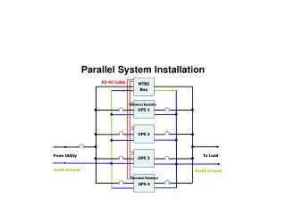
Procedure for AC Power Release to Rack Systems • Purpose: • To provide for safe AC power application to the individual rack distribution systems (plug molds, outlets, breaker panels, ect.) and equipment in the racks • Constraints: • Ensure that with the application of AC power to each rack no electrical hazards are created via rack equipment, cable plant or conductors (either within or leaving the rack). • Procedure • Identify/list all potential hazards, correct or neutralize any potential electrical hazard, request and receive approval from LCLS Controls Manager and the LCLS Installation Manager (R. M. Boyce) for the release/application of AC power to identified rack. • Once approval is given appropriate breakers will be unlocked and control of breakers turned over to responsible system engineer.
PP-6 After Contractor Turn-over & LCLS Safety Lockout PP-7 After Contractor Turn-over & LCLS Safety Lockout
Software Installation Status • All IOCs have loaded their software from a central EPICS file server. The server is ready to support pre-beam checkout and commissioning. • All controls software will be installed and checked out according to a “signed off” test plan. • Alarm Handler, Archiver, autosave/channelWatcher, Channel Access Security, and SCORE ready to support pre-beam checkout and commissioning • Software has been installed following the LCLS software RELEASE procedure.
Issues & Concerns • Schedule & Resources • Controls is the systems “integrator” – delays in other systems directly impact our installation. This has been the case in the Injector and BC2 installation phases • Support of operations while completing final installation and pre-beam checkout of LTU/UND/EDMP • System Functionality • The new MPS – pre-beam checkout will be tight
Summary • Controls in general is in good shape for 2008 installation • No major design or production issues dominate the plan • There are concerns about the transfer of systems from ANL to SLAC. • We will use BLMs from PEP (Thanks to Alan Fischer) • We have received a draft “HandOver” and a draft “Detailed Software Design Document” plan from ANL • A large number of sub-systems have been installed and pre-beam checkout is the major activity before Dec. 1, 2008