Download
1 / 12
120 likes | 215 Views
EUROFEL PROJECT. ENEA DS3 PARTICIPATION. Basic Considerations. Oscillator 80 MHz. Reg. Amplifier. Reg. Amplifier. Harmonic Generation. Cathode. Multipass Amplifier. Basic Considerations. In the SPARC experiment the electron beam is 10 ps long and has a flat-top profile

E N D
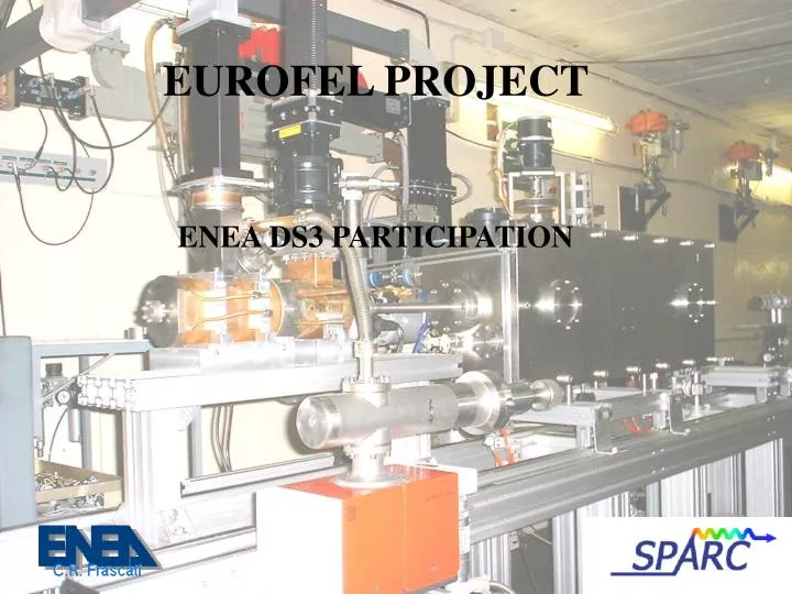
EUROFEL PROJECT ENEA DS3 PARTICIPATION
Basic Considerations Oscillator 80 MHz Reg. Amplifier Reg. Amplifier Harmonic Generation Cathode Multipass Amplifier
Basic Considerations • In the SPARC experiment the electron beam is 10 ps long and has a flat-top profile • The seed radiation is very short, about 100 fs • A jitter of +/- 1 ps is tolerable in SPARC, but in future, will be compressed down to 1 ps time range, thus the jitter requirements will get tighter.
Activities In order to evaluate the synchronization process in seeded high gain FEL, a measuring technique will be developed exploiting the properties of the radiation generated in the magnetic undulator. A second technique will be studied in order to measure the jitter of both the electron beam and the UV seed generated by the high harmonic generation process in gas or crystals. In order to perform both measurements a delay line system is needed between the electron beam and the UV seed. The delay adjustment allows the overlapping between the electron bunch and the radiation seed at the undulator entrance.
Delay Line The Regenerative Amplifier is excited at 1 KHz but the Pockel’s cells are enabled by the e-gun trigger at 10 Hz. The Amplifier cavity round trip is about 7 ns that thus correspond to the uncertainty exit time for the amplified Ti:Sa pulse. Reg. Amplifier Ti:Sa @ 10 Hz Crystal/Gas Harmonic Generator 1 ns 7 ns
Synchronization Measurements A perfect synchronization is realized when a maximum power for the radiation generated at the undulator exit is recorded. 160 nm – 20 kW Undulator length for the power measure must be chosen in order to maximize the differences between the SASE process and the seeding process. 160 nm – 5 MW
Jitter Measurements I For the jitter measurement it is necessary to desynchronize the seed respect to the electron beam and then analyze the envelope of the longitudinal width, of both the signals, during a long time measurement. Streak Camera
Jitter Measurements II Non Linear Medium Spatial Profile Time Profile
Experimental Setup Quadrupol Undulator Undulator Diagnostics Chamber Streak Camera CCD Cameras And Detectors
Optical Line in the SPARC Hall Sala SPARC Sala Macchine Inferiore