Download
1 / 22
220 likes | 264 Views
Explore how the SPICE instrument on the Solar Orbiter mission captures unprecedented solar imagery, its critical bonding process, and challenges faced and overcome. Discover its significance in studying solar effects on Earth and space weather.

E N D
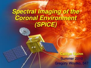
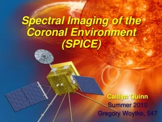
Spectral Imaging of the Coronal Environment(SPICE) Caitlyn Quinn Summer 2010 Gregory Woytko, 547
What is SPICE? • Imaging coronal spectrograph • One of ten instruments to fly on the ESA/NASA Solar Orbiter mission in 2017 • Will orbit the sun at closest distances ever attempted, around 1/4 AU • SPICE instrument currently in Phase A
Solar Orbiter Mission Goals • Evaluate plasma properties and composition of the sun with unprecedented spatial and spectral resolution • Improve our understanding of the Sun’s effects on Earth and the solar system • Better understand CME and space weather
Orbit .23 AU
The Instrument • Sun’s light comes in through entrance aperture • Ray hits primary mirror and series of optics • Pre-slit deflects excess radiation • Ray passes through slit mechanism; four slits of varying width • Detectors interpret incoming EUV light
The Detector • Spring-loaded door • 2 detector stacks MCP HAS FOC
Detector Stacks • Micro Channel Plates (MCP) • High voltage • Fiber Optic Coupler (FOC) • Transmits/focuses image • HAS chip • Intensified active pixel sensors • Off-centered active area • Components in stack connected by epoxy bond lines MCP FOC HAS
The Detector • Door opens, EUV radiation hits MCPs • MCPs are supplied a high voltage, detect and amplify incoming radiation • Radiation and voltage transmit through FOC to HAS chip • High voltage activates HAS pixels, which record incoming signal
Bonding the Detector Together • Epotek 310M Epoxy • Plastic adhesive • Transparent, maintains maximum strength down to 10-12 m • Connection between HAS and fiber optic coupler is CRITICAL • Determines resolution of images captured CRITICAL bond line
Critical Bond: FOC to HAS • FOC focus: 4 m • HAS pixels: 18 m • Light refracts 30° on either side of ray from the FOC to epoxy • Distance between FOC and HAS (i.e. bond thickness) determines spread • Smaller spread, better resolution
Critical Bond: FOC to HAS Worst case scenario: bond line 12 m, single focused ray spreads over multiple HAS pixels
Issues With Bonding • ESD sensitivity of HAS • Accuracy, precision • How to ensure precise placement of FOC in active area despite slight variations in HAS chips? • 2 bonds on one FOC • Expense of HAS • Only get “one shot” to do it right during actual fabrication Solution??
Bonding Fixture • Grounded metal plate with HAS-shaped pocket • Outer holes to secure fixture and ground plate • Holes around pocket for T-shaped alignment bars (adjustable) • HAS is removable after bonding is achieved • Drawings approved, quote received, solid models in the making!
SPICE: General Issues • Ability of instrument to withstand wide range of temperatures • Will the detector and bonds withstand testing: vibration, thermal, acoustic, etc? • Passing upcoming CDR • Delayed execution of instrument (>3 yrs)
Other Experiences at NASA • Working alongside engineers, scientists, machinists • Clean room training • Disassembling hardware • Machine Shop • ESDM • 5-axis milling • Metrology, FARO arms • Rapid prototyping: SLA