Download
1 / 46
460 likes | 475 Views
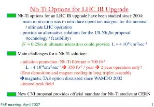
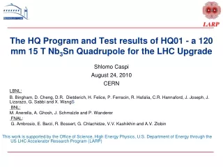
Explore HQ01 quadrupole magnet test results for LHC's upgrade, supported by US Department of Energy and LARP program.

E N D
The HQ Program and Test results of HQ01 - a 120 mm 15 T Nb3Sn Quadrupole for the LHC Upgrade Shlomo Caspi August 24, 2010 CERN LBNL: B. Bingham, D. Cheng, D.R. Dietderich, H. Felice, P. Ferracin, R. Hafalia, C.R. Hannaford, J. Joseph, J. Lizarazo, G. Sabbi and X. WangS BNL: M. Anerella, A. Ghosh, J. Schmalzle and P. Wanderer FNAL: G. Ambrosio, E. Barzi, R. Bossert, G. Chlachidze, V.V. Kashikhin and A.V. Zlobin • This work is supported by the Office of Science, High Energy Physics, U.S. Department of Energy through the US LHC Accelerator Research Program (LARP)
Outline S. Caspi • Introduction – The LARP program • The HQ magnet • Test results – HQ01a, HQ01b • Conclusions and Future Plans
LARP – Program Goals LHC Accelerator Research Program (LARP): • Started in 2004, expected to be completed around 2014 • Collaboration of four national Labs: BNL, FNAL, LBNL, SLAC • Funding level: $12-13M/year (FY06-FY10) Program Goals: • Extend and improve the performance of the LHC • Maintain and develop US Labs capabilities • Advance international collaboration on large accelerator projects Magnet Goals: • Demonstrate that Nb3Sn technology is a viable option for the LHC phase II upgrade. S. Caspi
LARP - Magnet R&D Program • 1. Nb3Sn Technology - TQ • Conductor studies • Coil fabrication • Mechanical support • Modeling tools • Quench protection Reached 238 T/m • 2. Length scale-up - LQ • Coil technology • Quench protection • 3. Design optimization - HQ • Larger aperture • higher energy and forces • Accelerator quality S. Caspi
HQ Program & Targets Program • Part of the US LHC Accelerator Research Program (LARP) • Develop Nb3Sn quadrupole magnet for the LHC luminosity upgrade. Magnet • Extend Nb3Sn magnet technology: • from 1 m long, 90 mm bore, 13T -> TQ – field quality • to 1 m long, 120 mm bore, 15T -> HQ + field quality • HQ operating point 80% of ss: • 160 (T/m) at 4.4K • 175 (T/m) at 1.9K • Good memory – no retraining Conductor • Evaluate different strands (54/61 and 108/127 filaments). S. Caspi
The HQ Collaboration Program • A collaboration between 3 US laboratories and CERN: • BNL – • Tooling design - reaction, impregnation, shipping • Coil work - react, instrument and impregnate (50-50% BNL/ LBNL) • FNAL – • Magnetic cross-section design • Design and fabrication of all islands, end spacers and shoes • HQ magnet test and single coils mirror test • LBNL – • Coil winding, curing, reaction, instrumentation, impregnation. • Design, analysis and fabrication of structure • Magnet assembly and Test • Tooling design and fabrication • CERN • Test S. Caspi
TQ-HQ Similarities and Differences • HQ • 120mm bore, 15mm cable • 15T + alignment + field quality • keys bladders assembly • Al shell • Axial Al rods • +Al collars + alignment keys • + layer 1 TQ- (shell/Collar) C/S* • 90mm bore, 10mm cable • Peak field 13T, no alignment • Keys & bladders / press assembly • Az. pre-stress - SS shell / Al shell • Axial load - end plates / Al rods • Pads without alignment • Protection heaters – layer 2 only *C is collar structure S is shell structure S. Caspi
HQ Progress 2008 June Presented conceptual designs for 114 and 134 mm bore July Selection of 120 mm quadrupole aperture for Phase 1 Sept. Cable and coil cross-section geometry finalized Dec. All coil fabrication tooling in procurement 2009 Mar. All coil and structure components in procurement Apr. Cables for ~10 coils fabricated (54/61 and 108/127) Sept. Coil 1 completed and coil 2 wound Dec. Coil 2 completed, coil 3-4 reacted, coil 5 wound 2010 Jan. Structure pre-assembly completed Feb Coil 1-4 completed Mar Assembly completed Apr. HQ01a test coils 1-4 results June HQ01b test coils 1,4,5,6 results Present Aug. Coils 1-9 completed, 10 underway Dec 12 coils completed and 3-4 tests S. Caspi
HQ Parameters S. Caspi 10/28/2019
HQ - Coil S. Caspi
HQ – Alignment Keys Alignment keys for field quality 10/28/2019 S. Caspi
HQ – Aluminum Collars • Assemble the coils, • Displace the yoke to reduce saturation effects S. Caspi
HQ – Iron Pads Iron pads complete the coil subassembly 10/28/2019 S. Caspi
Merging two subassemblies Coil subassembly is placed within the structure subassembly 10/28/2019 S. Caspi
Final Assembly and Pre-stress Four “Masters” are used to align and pre-stress the two subassemblies during the key and bladder operation 10/28/2019 S. Caspi
LARP – HQ Cross-Section • 0.8 mm strand • 15 mm wide cable • 120 mm bore • 4.4 K/1.9 K -195/214 T/m • 4.4 K/1.9 K – 13.7/14.9 T S. Caspi
Room temperature before loading S. Caspi 10/28/2019
Bladder operation Gap opening between load key and pad master * Large scale factor to simulate displacements S. Caspi 10/28/2019
Key insertion Shimming of the load key with 600 mm stainless steel shims * Large scale factor to simulate displacements S. Caspi 10/28/2019
Cool-down DR of 270 mm * Large scale factor to simulate displacements S. Caspi 10/28/2019
With Lorentz forces at 219 T/m DR of 78 mm * Large scale factor to simulate displacements S. Caspi 10/28/2019
ANSYS 3D Analysis • Axial pre-load • Azimuthal pre-load • Cool-down • Excitation Low pre-stress during assembly Cool-down and high pre-stress No stress overshoot Reusable structural components S. Caspi 10/28/2019
HQ - Average Azimuthal Stress Average stress in HQ is 140 MPa but local stress expected to exceeds 200 MPa TQS performed above 90% , 150 MPa average stress and over 200 MPa local stress MPa -212 -188 -164 -140 -116 -92 -68 R=120 mm -44 R=90 mm -20 10/28/2019 S. Caspi
Coil Preparation and Fabrication CAD Rapid Prototyping (RP) Wire EDM 10/28/2019 S. Caspi
Winding and Curing Coil Winding Curing Cured Layer 1 S. Caspi
Reaction Tooling • 72 hr at 210 C • 48 hr at 400 C • 48 hr at 665 C Post Reaction: NbTi Leads, VT, SG. Iimpregnation Tooling 10/28/2019 S. Caspi
Impregnated Coil (PC1) 10/28/2019 S. Caspi
Coils Assembly and Alignment Alignment Keys Coil & heater Collars S. Caspi
HQ01a – ready to test Aluminum shell + strain-gages S. Caspi
HQ01a Measured Stress S. Caspi 10/28/2019
HQ01a/b performance HQ01a Q1 - 12183A (141T/m, 71% of ss) Q11 - 13683A (157T/m, 79% of ss) HQ01b Q1 - 13308A (153T/m, 77% of ss) HQ01a - all quenches in coil #3 S. Caspi 10/28/2019
HQ01b Training at 4.4K Linear behavior of coils azimuthal stress versus shell Linear behavior of coils azimuthal stress with current square S. Caspi
Voltage Activity During a Quenchand an Impulse Test Protection heaters fire Voltage Breakdown Voltage Impulse test on a damaged coil showing arcing activity S. Caspi 10/28/2019
HQ01a Test – Coil #2 • Although Coil #2 never quenched visual damage is seen on the outer layer from to island S. Caspi 10/28/2019 34
HQ01b Test – Coil #6 • Voltage breakdown at the return-end of coil #6 between next to shoes. • This location exhibits the highest voltage difference within a coil as well as high risk location when both layers and both shoes meet at one spot. Top view Side view S. Caspi 10/28/2019 35
HQ End Potential hazards are nesting outer blocks and local convergence of the outer most turns of both layers and their shoes. S. Caspi
Impulse Tests on HQ Coils • Coils #1,2,3,4,5,7 went through an impulse test (#6 was cut) • Coils #1,3,5,7 passed • Coil #2,4 failed • Coils for HQ01c test • Use coils #1,3,5,7. Since coil #3 was a limiting coil during HQ01a it is conceivably it will limit the magnet plateau. • The test is to confirm detection of inter-coil high voltage risks S. Caspi
Coil1 Coil4 10ms Coil5 Coil7
Coil 3 Whole coil voltage at the start of ramping. Vmax = 110V Coil 3 Whole coil voltage at the end of ramping. Vmax = 1100V
Full ramping on coil 4 Higher peaks indicate arcing Abnormal drop 1 second
First instance of arcing in coil 4 10ms S. Caspi
Full ramping on coil 2 Higher peaks indicate arcing
Coil 2 Whole coil voltage at the start of ramping. Vmax = 105V Coil 2 Whole coil voltage at the end of ramping. Vmax ~ 650V
Coil 2 Arcing Zoom-in
Future Impulse Tests • BNL/FNAL/LBNL start doing impulse tests • Impulse test on previous TQ/LQ coils • Impulse tests involve risks, short pulses do not remove the risk. S. Caspi
HQ Summary • A 120 mm bore, Nb3Sn quadrupole is under construction and testing • The magnet is optimized for alignment and field quality • Magnet is expected to reach ~215 T/m at 1.9 K • The first tests of HQ01a/b achieved expected mechanical performance and intermediate gradients of 153-157T/m • Performance overshadowed by voltage breakdown in end-regions . • Need to re-evaluate risks - reduce hi-pot voltage, increase layer-to-layer and coils-to-shoes insulation, add voltage impulse tests • The next test, HQ01c – verify magnet performance with coils that passed voltage impulse tests (#1,3,5,7). S. Caspi