Download
1 / 18
180 likes | 294 Views
This briefing outlines Alion's experiment to investigate anomalous propagation around the Wallops Command and Data Acquisition Station (WCDAS) due to potential radio frequency interference (RFI) from 4G mobile broadband systems. The study will evaluate atmospheric conditions affecting signal propagation and assess the impact of external factors on NOAA's satellite communications spectrum. Proposed actions include deploying L-band transmitters at coastal locations and setting up monitoring equipment at WCDAS to collect weather data. Collaboration with Rutgers is anticipated to enhance the utility of the gathered data.

E N D
Anomalous Propagation ExperimentBriefing Alion Science and Technology Nathan Hall 240-646-3571 January 24, 2014
Background • Purpose • Anomalous Propagation • Test Plan • Proposed Transmit Site Locations • Transmit Site Equipment • Monitoring Equipment at WCDAS • Support • Way Forward • Data Beneficial to Rutgers Slide1 Overview of Briefing
Slide2 • NOAA’s weather satellite communications spectrum being encroached upon (National Broadband Plan) • NTIA to auction off 1695 – 1710 MHz (NOAA’s band is 1670 – 1710 MHz) • Alion analyzed NTIA plan to share 1675 – 1710 MHz with proposed 4G mobile broadband cellular systems • NTIA determined a relatively small coordination zone (26 km) for one of NOAA’s main ground stations, Wallops Command and Data Acquisition Station (WCDAS), located in Wallops, VA • Alion believes WCDAS downlinks will receive radio frequency interference (RFI) from sources outside the 26 km coordination zone Slide2 Background
Alion wants to investigate anomalous propagation in the area around WCDAS • Prove anomalous propagation occurs around WCDAS area • Prove that weather data received at WCDAS could be compromised by RFI generated by 4G mobile broadband cellular systems/networks that are located along the east coast Purpose
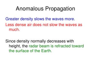
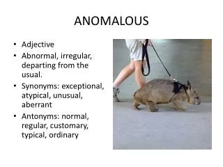
Slide4 Slide4 • Phenomena that occur when non-standardatmospheric conditions enhance signal propagation • One form known as “ducting” • Often occurs near waterwhen atmospheric conditions create a marine layer or duct that allows microwave signals to refract along distances longer than line-of-sight (LOS) Anomalous Propagation
Slide5 • Deploy multiple low-power (3 – 5 Watts) L-band (1688 – 1690 MHz) transmitters in coastal regions near the WCDAS (within several hundred miles) • Transmitters located beyond LOS from WCDAS • Each transmitter uniquely tagged for identification • Monitoring equipment set up at WCDAS to receive transmissions • 12 month (or longer) duration • Begin with close-proximity transmit locations and eventually branch out to greater distances Slide5 Test Plan
Table shows MARACOOS sites proposed and the phases of the experiment in which they would be used as transmitter sites Oceanographic Radar (MARACOOS) Sites
Steel Tower - 10 to 15 ft high • Solar panel • Log-periodic array antenna • 12 VDC battery • NEMA box that houses radiosonde transmitter, solar panel, controller, 3 – 5 W power amplifier • Transmit cycles 2 mins; 3 – 4 times an hour, 24 hrs/day • Frequencies (Phase A): 1688.1, 1688.5, 1689, 1689.5, 1689.9 MHz • Longer term frequencies (Phase B): Every 100 kHz, (e.g. 1688.2, 1688.3, 1688.4, etc. up to 1689.9 MHz) Transmit Site Equipment
Transmit Site Equipment (cont’d) Antenna Solar panel Battery NEMA Box
Place Yagi antennas on 150-foot tower in antenna field • Twelve antennas total (4 at each level) • Low-noise amplifier (LNA) after each antenna • Four antennas at heights of 50 ft, 100 ft, and 150 ft (pointed in different azimuth sectors) • Antennas at each level summed into one output • Separate receiver for each height • Monitoring equipment shelter at base of tower • Monitor 1688 – 1690 MHz transmit band 24 hours a day • Identify transmission ID, time, and location (temperature, pressure, and humidity data also received) • Data can be remotely retrieved nearly instantaneously Monitoring Equipment at WCDAS
Permission to place transmitter towers at proposed MARACOOS sites • Understand that none of the property is owned by MARACOOS or Rutgers • In that case, any information that would assist in gaining permission from property owners Rutgers/MARACOOS Support
Gain permission from Rutgers/MARACOOS/site property owners to use MARACOOS sites • Deploy Phase A transmitters • Currently have 10 transmitter configurations ready • Set up monitoring equipment at WCDAS • Monitor Phase A transmitters for several months • Deploy Phase B transmitters Way Forward
Radiosonde transmitters that Alion is using as their test transmitters are regularly used in weather balloons to collect various weather data • Temperature, pressure, and humidity • Radiosondes also contain GPS • Alion has no problem sharing this weather data that would be collected over the duration of our experiment with Rutgers if they find they have a use for it Data Beneficial to Rutgers
Nathan Hall, engineer, 240-646-3571; nhall@alionscience.com Lawrence Crippen, project manager, 410-703-0078; lcrippen@alionscience.com Contacts