Download
1 / 12
150 likes | 347 Views
Organic Light-Emitting Diodes(OLED) on Solution-Processed Graphene Transparent Electrodes. Wu, J.; Agarwal , M.; Becerril , H. A.; Bao, Z.; Liu, Z.; Chen, Y.; Peumans , P . ACS Nano 2010 , 4, 43–48. Graphene VS. Indium tin-oxide (ITO ). Outline. Introduction to OLED

E N D
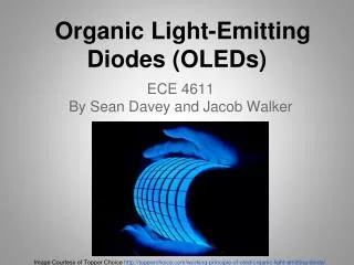
Organic Light-Emitting Diodes(OLED) onSolution-Processed GrapheneTransparent Electrodes Wu, J.; Agarwal, M.; Becerril, H. A.; Bao, Z.; Liu, Z.; Chen, Y.; Peumans, P. ACS Nano2010, 4, 43–48 Graphene VS. Indium tin-oxide (ITO)
Outline • Introduction to OLED • Disadvantages of ITO • Experimental results • Simulated results
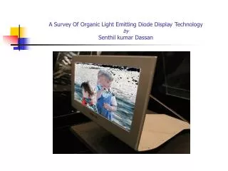
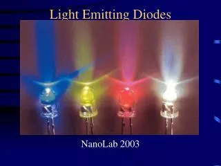
Introduction to OLED • Working principle • Application (thinner, brighter and more flexible)
Disadvantages of ITO • Expensive the cost of indium and the low throughput deposition process • Hard (not flexible) metal oxides such as ITO (about 150 nm thick to ensure electrical performance) are brittle and therefore of limited use on flexible substrates • Metal Diffusion indium is known to diffuse into the active layers of OLEDs, which leads to a degradation of performance over time Looking for other transparent electrodes……
Alternative transparent electrodes potentials for thin transparent electrodes this work: ~7nm thick, , at 550nm
Graphene film preparation • Graphene Oxide(GO) dispersed in water A graphite crystal Graphitic Oxide GO • Spin coating on the quartz • Reducing GO by vacuum annealing
Graphene vs. ITO--Experimental results • Current density and luminance computer display 50~300 cd/m2 Graphene ITO 0.02 4.5V 3.8V 300 11.7V 9.9V Similar performance despite the higher sheet resistance and different workfunction
Graphene vs. ITO--Experimental results • External Quantum Efficiency(EQE) and Luminous Power Efficiency (LPE) The nearly identical EQE is surprising because the fraction of optical power that couples out of an OLED structure depends strongly on the thickness of the various layers
Graphene vs. ITO--Simulated results • Various optical modes generated ST---substrate trapped modes WG---wave-guided modes SPP-surface plasmon polariton UB---unbound air modes
Graphene vs. ITO--Simulated results • Spectral and angular dependence Lambert’s cosine law and equal brightness effect
Graphene vs. ITO--Simulated results • Power distribution with wavelength and in-plane wave-vector differences in layer structure no WG in Graphene
Conclusion • The electrical and optical performance of a small molecule OLED on graphene is similar to that of control devices on ITO