Download
1 / 73
740 likes | 868 Views
Input/Output. 5.1 Principles of I/O hardware 5.2 Principles of I/O software 5.3 I/O software layers 5.4 Disks 5.5 Clocks 5.6 Character-oriented terminals 5.7 Graphical user interfaces 5.8 Network terminals 5.9 Power management. Chapter 5. I/O Device.

E N D
Input/Output 5.1 Principles of I/O hardware 5.2 Principles of I/O software 5.3 I/O software layers 5.4 Disks 5.5 Clocks 5.6 Character-oriented terminals 5.7 Graphical user interfaces 5.8 Network terminals 5.9 Power management Chapter 5
I/O Device • I/O devices can be divided into two categories: • A block devices is one that stores information in fixed-size blocks. • A character device delivers or accepts a stream of characters, without regard to any block structure. • Some devices do not fit in: clocks, memory-mapped screens.
Principles of I/O Hardware Some typical device, network, and data base rates
Device Controllers • I/O devices have components: • mechanical component • electronic component • The electronic component is the devicecontroller or adapter. • may be able to handle multiple devices • On PCs, it often takes the form of a printed circuit card that can be inserted into an expansion slot. • Controller's tasks • convert serial bit stream to block of bytes • perform error correction as necessary • make available to main memory
Memory-Mapped I/O • Each controller ha a few registers that are used for communicating with the CPU. The operating system can command the device by writing into these registers and learn the device’s state by reading from these registers. • Many devices have a data buffer that the operating system can read and write. Two approaches exist: • Each control register is assigned an I/O port number. • All the control registers are mapped into the memory space. This is called memory-mapped I/O.
Memory-Mapped I/O • Separate I/O and memory space • Memory-mapped I/O – PDP-11 • Hybrid - Pentium
Memory-Mapped I/O • Advantages of memory-mapped I/O: • An I/O device driver can be written entirely in C • No special protection mechanism is needed to keep user process from performing I/O. • Every instruction that can reference memory can also reference control register. • Disadvantages of memory-mapped I/O: • Caching a device control register would be disastrous (not reflect current device status change). • All memory modules and all I/O devices must examine all memory references.
Memory-Mapped I/O (a) A single-bus architecture (b) A dual-bus memory architecture
Direct Memory Access (DMA) • Direct Memory Access (DMA) is a capability provided by some computer bus architectures that allows data to be sent directly from an attached device (such as a disk drive) to the memory on the computer's motherboard. • DMA operations: • CPU program the DMA controller • DMA requests transfer to memory • Data transferred • The disk controller sends an acknowledgement
Direct Memory Access (DMA) Operation of a DMA transfer
Interrupts Revisited • The interrupt vector is a table holding numbers on the address lines specifying devices. • Precise interrupt: • The PC (Program Counter) is saved in a known place. • All instructions before the one pointed to by the PC have fully executed. • No instruction beyond the one pointed to by the PC has been executed. • The execution state of the instruction pointed to by the PC is known.
Interrupts Revisited How interrupts happens. Connections between devices and interrupt controller actually use interrupt lines on the bus rather than dedicated wires
Principles of I/O SoftwareGoals of I/O Software • Device independence • programs can access any I/O device • without specifying device in advance • (floppy, hard drive, or CD-ROM) • Uniform naming • name of a file or device a string or an integer • not depending on which machine • Error handling • handle as close to the hardware as possible
Goals of I/O Software • Synchronous vs. asynchronous transfers • blocking transfers vs. interrupt-driven • Most physical I/O is interrupt-driven. • Buffering • data coming off a device cannot be stored in final destination • Sharable vs. dedicated devices • disks are sharable • tape drives would not be
I/O Execution • There are three ways that I/O are performed: • Programmed I/O • Disadvantage: tying up the CPU full time until all the I/O is done. • Interrupt-driven I/O • Interrupts might waste time. • I/O using DMA • Slower than CPU
Programmed I/O • Steps in printing a string • String in the user buffer • A System call to transfer the string to the kernel. • String printed
Programmed I/O Writing a string to the printer using programmed I/O
Interrupt-Driven I/O • Writing a string to the printer using interrupt-driven I/O • Code executed when print system call is made • Interrupt service procedure
I/O Using DMA • Printing a string using DMA • code executed when the print system call is made • interrupt service procedure
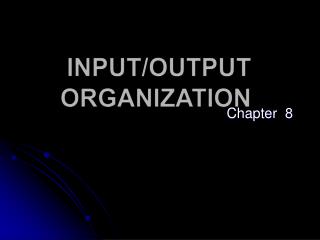
I/O Software Layers • I/O Software in four layers: • Interrupt handlers • Device drivers • Device-independent operating system software • User-level I/O software
I/O Software Layers Layers of the I/O Software System
Interrupt Handlers • Interrupt handlers are best hidden • have driver starting an I/O operation block until interrupt notifies of completion • Interrupt procedure does its task • then unblocks driver that started it
Interrupt Handlers • Steps must be performed in software after interrupt completed • Save registers not already saved by interrupt hardware • Set up context for interrupt service procedure • Set up stack for interrupt service procedure • Acknowledge interrupt controller, reenable interrupts • Copy registers from where saved • Run service procedure • Set up MMU context for process to run next • Load new process' registers • Start running the new process
Device Driver • The device driver is the device-specific code for controlling the I/O device attached to a computer. • Current operating systems expect drivers to fun in the kernel. • Operating systems usually classify drivers into: • Block devices • Character devices
Device Drivers • Logical position of device drivers is shown here • Communications between drivers and device controllers goes over the bus
Device-Independent I/O Software Functions of the device-independent I/O software
Device-Independent I/O Software (a) Without a standard driver interface – a lot of new programming effort (b) With a standard driver interface
Buffering • Buffering is a widely-used technique. If data get buffered too many times, performance suffers. • Classes of I/O errors: • Programming errors • Actual I/O errors • Some I/O software can be linked with user programs. • Spooling is a way of dealing with dedicated I/O devices in a multiprogramming system. • A spooling directory is used for storing the spooling jobs.
Device-Independent I/O Software (a) Unbuffered input (b) Buffering in user space (c) Buffering in the kernel followed by copying to user space (d) Double buffering in the kernel
Device-Independent I/O Software Networking may involve many copies
User-Space I/O Software Layers of the I/O system and the main functions of each layer
Disks • Disks come in a variety of types: • Magnetic disks (hard disks and floppy disks) • Arrays of disks • Optical disks • CD-ROMs • CD-Recordables • CD-Rewritables • DVD
DisksDisk Hardware Disk parameters for the original IBM PC floppy disk and a Western Digital WD 18300 hard disk
Disk Hardware • Physical geometry of a disk with two zones • A possible virtual geometry for this disk
Disk Hardware • Raid levels 0 through 2 • Backup and parity drives are shaded
Disk Hardware • Raid levels 3 through 5 • Backup and parity drives are shaded
Disk Hardware Recording structure of a CD or CD-ROM
Disk Hardware Logical data layout on a CD-ROM
Disk Hardware • Cross section of a CD-R disk and laser • not to scale • Silver CD-ROM has similar structure • without dye layer • with pitted aluminum layer instead of gold
Disk Hardware A double sided, dual layer DVD disk
Disk Formatting A disk sector
Disk Formatting An illustration of cylinder skew
Disk Formatting • No interleaving • Single interleaving • Double interleaving
Disk Arm Scheduling Algorithms • Time required to read or write a disk block determined by 3 factors • Seek time • Rotational delay • Actual transfer time • Seek time dominates • Error checking is done by controllers
Disk Arm Scheduling Algorithms Pending requests Initial position Shortest Seek First (SSF) disk scheduling algorithm
Disk Arm Scheduling Algorithms The elevator algorithm for scheduling disk requests
Error Handling • A disk track with a bad sector • Substituting a spare for the bad sector • Shifting all the sectors to bypass the bad one
Stable Storage Analysis of the influence of crashes on stable writes
ClocksClock Hardware A programmable clock
Clock Software (1) Three ways to maintain the time of day