Download
1 / 39
400 likes | 531 Views
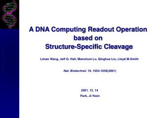
DNA Computing and Robotics Based on Deoxyribozymes. DAO-E Sierpinski triangle experiments. Paul Rothemund, Nick Papadakis, Erik Winfree, PLoS Biology 2: e424 (2004). 340nm. Part 1: How do we program mixtures of molecules in solution?

E N D
DNA Computing and Robotics Based on Deoxyribozymes
DAO-E Sierpinski triangle experiments Paul Rothemund, Nick Papadakis, Erik Winfree, PLoS Biology 2: e424 (2004) 340nm
Part 1: How do we program mixtures of molecules in solution? • Part 2: How do we program behavior of an individual molecule?
Joyce 1995, 1997 Introduction to deoxyribozymes: Single stranded DNA (or RNA) Complementary
Introduction to deoxyribozymes II: Joyce 1995, 1997
…into a two-state switch: Detector gate or sensor or YES gate or …
i3 Complete set of switches: NOT Gate: AND Gate: ANDANDNOT:
Before we give examples of gates, a reminder: 1 is an increase in fluorescence, 0 no such increase!
A bit more about FRET: Cleavage
250000 200000 150000 FU 100000 50000 0 0 100 200 300 400 t (min) Catalytic Molecular Beacons as Sensor Gates Stojanovic et al., ChemBioChem 2001 Stojanovic et al., J. Am. Chem. Soc. 2002 Joyce 1995, Breaker 1999, Tyagi, Kramer 1996
200000 150000 100000 FU 50000 0 0 100 200 300 t(min) NOT Gates – Inverters: Stojanovic et al., J. Am. Chem. Soc. 2002
FU t(min) Dual Input Molecular Computation Elements: AND Gate
Triple Input Elements: ANDAND Harvey Lederman
Before we give examples of gates, a reminder: 1 is an increase in fluorescence, 0 no such increase!
A + X = O 0 1 0 0 1 2 1 01 00 01 00 00 01 10 GR GR GR i1 i2 Let’s add A (0 or 1) and X (0 or 1) and get O (0 or 1, or 2):
10 01 2 1 Implement addition with gates: Stojanovic & Stefanovic, J. Am. Chem. Soc. 2003
1 Now, a twist: 1 is an increase in fluorescence, 0 no such increase!
Segments required d1 d2 d3 d4 d5 d6 d7 d8 d9 Here is 7-segment display: J. Macdonald, Columbia University
Binary inputs Non general Display output A1 A0 + X1 X0 1+1: 0 1 + 0 1 = 1+2: 0 1 + 1 0 = 2+1: 1 0 + 0 1 = 2+2: 1 0 + 1 0 = More arithmetical operations: Test by constructing simple 2+2-bit adder Expected display Adder result “hard-wired” into decoder Designate 4 oligonucleotides as binary inputs J. Macdonald, Columbia University
Adding 2+2 with visual display: • Determine logic gates required, and layout in wells (via Microsoft Excel) • Very simple logic gate arrangement required: • 4 YES gates • 2 AND gates • Fully constructible from reagents in freezer • Tested with all input combinations…. J. Macdonald, Columbia University
Adding 2+2 with visual display: (A1A0 + X1X0 display) 01+01= 01+10= 10+01= 10+10= Binary inputs: No inputs Perfect digital behavior Constructed & tested in a single day Fluorescence reader ~20-30mins 7-segment Display B&W imager within ~1hr Color photograph ~5hrs (1+1=2) Arithmetic (2+1=3) (1+2=3) (2+2=4) Background J. Macdonald, Columbia University; DNA 13, 2007
2x2 multiplier with visual display: (A1A0× X1X0 display) Gate arrangement 19 gates required J. Macdonald, Columbia University
2x2 multiplier with visual display: (A1A0× X1X0 display) Color photography Binary inputs: 01 × 01 = 01 × 10 = 01 × 11 = 10 × 01 = 10 × 10 = 7-segment Display Arithmetic (1×1=1) (1×2=2) (1×3=3) (2×1=2) (2×2=4) Binary inputs: 10 × 11 = 11 × 01 = 11 × 10 = 11 × 11 = (00 × 00) 7-segment Display Arithmetic (2×3=6) (3×1=3) (3×2=6) (3×3=9) no input control J. Macdonald, Columbia University
MAYA: MAYA-II: MAYA-III: Silicomimetic automata project (MAYA): Stojanovic&Stefanovic. Nat.Biotech. 2003 Macdonald et al. Nano Lett. 2006 Pei, Matamoros, et al. in testing Human designed Computer designed Human designed Goal: Demonstrate power of molecular computing! Goal: What does it take to coordinate large number of gates? Goal: Field programmable arrays of gates! -Teaching “by example” -Selecting strategy (“carving”)
Implementation of tic-tac-toe playing algorithm with deoxiribozymes: Molecular Array of YES and ANDANDNOT Gates (MAYA) Stojanovic, Stefanovic, Nat. Biotech. 2003
MAYA vs. Milan: losing game Mg2+ From Sci. Am. 2008
Is it possible to have serial circuits? (Upstream enzyme) (downstream enzyme)
Intergate Communication : Ligase-Cleavase Stanka Semova, Dmitry Kolpashchikov
XOR IA O IB Ligase-cleaves XOR circuit: JACS 2005
What about cleavase-cleavase? b. product as activator a. Substrate as inhibitor d. product as inhibitor c. Substrate as activator Cf. Uri Alon, Nat. Rev. Genetics2007, 450 “Network Motifs: Theory and Experimental Approaches”
+inhibitor +inhibitor Connection type I: Substrate as inhibitor Ben-Tov, Tamburi
Connection type II: Product as activator +i,p +U MB +MB cont 50nM d-8-17, 500nM d-sub, 500nM stem-loop, 50nM up-8-17, 500nM input Renjun Pei
Connection type III: Substrate as activator +act +U cont 100nM E6, 500nM d-sub, 500nM activator, 50nM 8-17 Renjun Pei, Aihua Shen
Connection type IV: Product as inhibitor P +MB +U 100nM E6, 500nM d-sub, 250nM stem-loop, 50nM 8-17 Renjun Pei, Aihua Shen
AND cascade: p 2 Es E-1 E-2 2 inhs 100nM E6, 500nM d-sub, 350nM inh-1, 350nM inh-2, 50nM 8-17-1, 50nM 8-17-2
Now we can do signal threshold: one eq. 100nM D, 500nM d-sub, 20nM U, 200nM inhat time 180 minutes.
Circuits by Winfree’s group: In Inputs Input Translation Computational subcircuit Signal restoration