Download
1 / 25
250 likes | 348 Views
Building and utilizing a low-level accelerator model in simulations for beam loss studies. Includes power deposition analysis in cold parts and beam loss monitoring using ionization chambers and detectors.

E N D
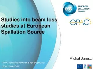
Studies into beam loss studies at European Spallation Source Michał Jarosz oPAC Topical Workshop on Beam Diagnostics Wien, 2014-05-09
I. Building an Accelerator (Model) • A low-level model in a simulation code: • Very useful in the design phase • Could remain useful during the operation • Can be started early as rough estimation and then updated regularly as more detailed information about the machine parts become available • Coherence – one model utilizing the whole machine; whith strict rules and common depository; modular build
I. Building an Accelerator (Model) heltankm 2 0 2 0. 0. 19.6 20.9 21.4 92.6 !middle part of helium tank helcovl 2 0 2 0. 0. 19.6 9.1 21.4 0.5 !helium tank left cover helcovr 2 0 2 0. 0. 111.7 9.1 21.4 0.5 !helium tank right cover magshld 2 0 8 0. 0. 19.45 24.25 24.4 92.9 !magnetic shield over cavities magshll 2 0 8 0. 0. 19.45 9.1 24.25 0.15 !magnetic shield left cover magshlr 2 0 8 0. 0. 112.2 9.1 24.25 0.15 !magnetic shield right cover termshld 2 0 9 0. 0. 0. 47.25 47.4 131.8 !thermal shield around
I. Building an Accelerator (Model) SPOKES ELLIPTICALS QUADS
I. Building an Accelerator (Model) Automated Generation (small python script)
I. Building an Accelerator (Model) Automated Generation (small python script) – as for now semi-automatic Planned integration with BLED (Beam Line Elements Database) Biggest dificulty – MARS representation of the elements
II. Using the accelerator model A. Studies on the power deposition in the cold parts • Three different loss paterns (uniform, smeared over the gap between cavities, located in the quadrupoles), all obeying 1 W/m rule • Verifying the 0.5 W/m limit for the power deposition in the cryocavities
II. Using the accelerator model A. Studies on the power deposition in the cold parts • Three different loss paterns (uniform, smeared over the gap between cavities, located in the quadrupoles), all obeying 1 W/m rule • Verifying the 0.5 W/m limit for the power deposition in the cryocavities
II. Using the accelerator model B. Determining the cryovalves life • Providing information about the dose absorbed by the element during normal, long operation of the accelerator
II. Using the accelerator model Results:
II. Using the accelerator model Results:
II. Using the accelerator model Results:
II. Using the accelerator model Results:
II. Using the accelerator model Results: Reminder to self: even being too conservative is sometimes possible !
III. Beam Loss Monitoring Beam loss monitoring at ESS: LHC-type ionization chambers in cold sections up to the target (well tested; known response functions; ordered)
III. Beam Loss Monitoring Beam loss monitoring at ESS: LHC-type ionization chambers in cold sections up to the target (well tested; known response functions; ordered)
III. Beam Loss Monitoring Beam loss monitoring at ESS: LHC-type ionization chambers in cold sections up to the target (well tested; known response functions; ordered) Ionisation chambers + additional lower energy detector in warm sections
III. Beam Loss Monitoring Beam loss monitoring at ESS: LHC-type ionization chambers in cold sections up to the target (well tested; known response functions; ordered) Ionisation chambers + additional lower energy detector in warm sections
III. Beam Loss Monitoring ? Beam loss monitors positioning ? ? ?
III. Beam Loss Monitoring Plans: Research on the front end, warm part to inspect BLM needs Fully automated accelerator model generation using BLED data Investigation on influence of x-rays from cavities on the detectors performance