Download
1 / 23
230 likes | 281 Views
This course project explores reconfigurable components in Software Defined Radio (SDR) RF front-end, focusing on antennas and practical examples of Planar Inverted Folded Antennas. Various electronically tunable and switched elements are discussed for frequency reconfigurability.

E N D
Reconfigurable Components In SDR RF Front-end With Emphasis On Reconfigurable Antennas A course project for Software Defined Radio CourseSpring 2008 By: MohamdFereidani Instructor: Professor M. J. Omidi Isfahan University of Technology
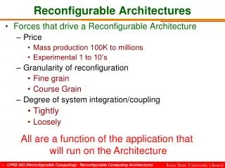
Fast Wide band Analog A/D D/A DSP Base band Narrow band reconfigurable Control Slow Analog A/D D/A DSP Base band Control RF front-end in SDR • Classical approach • Refined approach
Outline • Reconfigurable component solutions • Switched elements • Switch Technologies • Electronically tunable elements • Frequency reconfigurable antennas • Planar Inverted Folded Antennas (PIFA) • Practical examples of reconfigurable PIFA • Conclusion
Electronically tunable elements • Switched elements • Switches • below 1 GHz • PIN diode • 1GHz to 12 GHz • FET/HBT • DC-40GHz • MEMS Reconfigurable component solutions
Antenna solution for SDR • Wide band antenna • High cost, Trade off between size & efficiency, Weak noise and interferer blocking • Multi-narrow band antenna • Difficult design, Weak noise and interferer blocking, One design per application • Reconfigurable antenna • High noise and interferer blocking, There is some straightforward designs, Redesign is simple
Reconfigurable antenna • Frequency and bandwidth reconfigurable antenna • Most enabling component in SDR • PIFA antenna suits for small terminal • High efficiency (Power limitation ) • Compactness • Reconfigurable • Other reconfigurable antenna • Pattern or polarization reconfigurable • Can be used for improving performance • removing interferer, diversity, beam forming and etc
Planar Inverted F Antenna (PIFA) Inverted F Antenna (IFA) Planar Inverted-F Antennas (PIFA) • The planar version of the inverted-F antenna (IFA) • Compact height 1/20 wavelength • Typical bandwidth of 10% • Good relative radiation efficiency (max 40%) IFA PIFA
PIFA Resonant Frequency • Resonant Frequency affects by • current distribution on top plate (below Fig) • Top plate aspect ratio W/L • Shorting strap s • Height of top plate • S<<W • w/2<S<W
PIFA Bandwidth • Bandwidth affects by • Current distribution on ground plane (below Fig) • Length of ground plane • The bandwidth increases from 4% for a ground plane length of to 10% for a ground plane length of longer plane does not affect too much
Practical examples of reconfigurable PIFA (1) • SPA (shorted patch antenna) • In the case that operating frequency should be sweep on a narrow range and on discrete values. SPA is a good choice
Implemented SPA • It can switch between GSM850 & GSM900 • By switching the capacitor to the ground 25 mm 40 mm • Maximum antenna cross talk -20 dB
Practical examples of reconfigurable PIFA (2) • Varactor tunable PIFA antenna with U-shaped slot • In the case that operating frequency should be change in a relative wide range with continuous values Varactor tunable PIFA can be a good choice.
Varactor tunable PIFA antenna • L-shape structure suppresses the first resonance frequency by the outer element and create another new resonance frequency
Practical examples of reconfigurable PIFA (3) • In most cases operating frequency should be changed in a relatively wide rage • Common cellular band in Europe and USA • In such cases use of MEMS switched PIFA antenna can offer wide range tunability
Implemented MEMS switched PIFA Implemented antenna Simulation and measurement Results of S11 simulation measurement
Practical examples of reconfigurable PIFA (4) • Reconfigurable bandwidth PIFA Implemented antenna measurement Results of Return loss And pattern
Conclusion • For successful implementation of a multi-standard transceiver • reconfigurable architecture and reconfigurable component design technique are essential • Reconfigurable antenna offers good characteristics • PIFA antennas suit for small terminals • Reconfigurable, low power consumption, relative high efficiency, compact, high noise and interferer blocking
References [1] RF-MEMS for frequency agile software defined RF Systems, Bell Labs Europe Dr. Georg Fischer Consulting Member of Technical Staff Lucent, Nuremberg, 2006 [2] Small Terminal Antennas for Mobile Applications, Juan R.Mosig, AnjaK.Skrivervik, Marta Martinez-Vazquez, EPFL, CH-1015, Lausanne, Switzerland, IMST GmbH, Carl-Friedrich, Kamp-Lintfort, Germany, 2007 [3] A novel PIFA type varactor tunable antenna, Se-keun Oh, Yong-sun Shin, Seong-ook, Park School of engineering, Informations and communication University, Dae-jeon, Korea, 2007 [4] Active Antenna Bandwidth Control Using, Nathan P. Cummings, Virginia Tech Antenna Group, Bradley Department of Electrical & Computer Engineering, Blacksburg, Virginia, December 8, 2003 [5] RF MEMS And Their Applications, Vijay K. Varadan, K.J. Vinoy, K.A. Jose, Pennsylvania StateUniversity, USA, John Wiley & Sons Ltd, Reprinted April 2003 [6] A Small Multi-band MEMS Switched PIFA, K. R. Boyle, and P. G., Steeneken NXP Semiconductors Research, UK NXP Semiconductors Research The Netherlands, Progress In Electromagnetics Research Symposium 2007, Beijing, China, March 26-30 [7] Reconfigurable Antennas and RF Front ends for portable wireless devices, David T. Auckland, Shawn D. Rogers (Etenna Corporation, Laurel), James T. Aberle (Arizona State University) [8] Software Defined Radio, Edited by Walter Tuttlebee, 2002 John Wiley & Sons, Ltd
References [9] MEMS-Switched reconfigurable multi-band antenna: design and modeling, William H. Weedon and William J. Payne, Gabriel M. Rebeiz, Jeff S. Herd and Michelle Champion, 2000 [10] Design of MEMS based triple band antenna, Zahirul, Dept. of ECE, Faculty of Engineering, Dept. of ECE, Faculty of Engineering,2004 [11] Design of reconfigurable RF front-end for multi-standard receiver, Ji-Hoon Kim, Young-Kyun Jang, Hyung-JounYoo, Analog Integr Circ Sig Process, 2007 [12] Multi Band Frequency Synthesizer, BilelGassara, MahmoudAbdellaoui, NouriMasmoud, International Journal of Electronics, Circuits and Systems Volume 1 Number 3 [13] Fully-Integrated 10 GHz CMOS VCO for multi-band WLAN applicat, Laurent Perraud, Jean-Louis Bonnot, Nicolas Sornin, Christophe Pinate, NewLogic Technologies, 06906 Sophia Antipolis, France
Question ? Thank you
Trade offs Classical approach Wide band analog Fast digital system High level of blockers at A/D, high dynamic rage is required Linearity in both digital domain and analog domain is critical Fixed analog front-end Refined approach Narrow band analog Slow digital system Blockers shall be filtered at analog domain, so lower dynamic range is required at digital domain Linearity at digital domain is not critical, spurious signals shall be filtered Reconfigurable analog front-end Back up Silde
Quality factor of tuning capacitor has significant effect on efficiency and bandwidth Proximity of external lossy objects like a human operator’s head or hand decreases the efficiency In implemented SPA efficiency decreased by 15% instead of 30-40% SPA design considerations Back up Silde
MEMS switched PIFA • MEMS switched PIFA and its circuit A: switch connection for frequency tuning C: switch connection for impedance matching D: antenna feed Actuation voltage Back up Silde