Download
1 / 113
1.14k likes | 1.28k Views
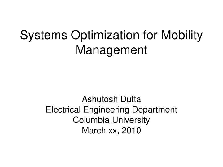
Systems Optimization for Mobility Management. Ashutosh Dutta Electrical Engineering Department Columbia University March xx, 2010. Outline. Motivation Vision Key Contributions Sample results Conclusions and Future work. Motivation.

E N D
Systems Optimization for Mobility Management Ashutosh Dutta Electrical Engineering Department Columbia University March xx, 2010
Outline • Motivation • Vision • Key Contributions • Sample results • Conclusions and Future work
Motivation • Cellular mobility typically involves handoff across homogeneous access technology • Optimization techniques are carefully engineered to improve the handoff performance • IP-based mobility involves movement across access technologies, administrative domains, at multiple layers and involve interaction between multiple protocols • Mechanisms and design principles for optimized handover are poorly understood • Currently there are ad hoc solutions for IP mobility optimization, not engineering practice • No formal methodology to systematically discover or evaluate mobility optimizations • No methodology for systematic evaluation or prediction of "run-time" cost/benefit tradeoffs
207.3.232.10 Mobile Host 128.59.11.8 207.3.232.10 128.59.10.7 128.59.9.6 802.11 802.11 207.3.240.10 900 ms media interruption 802.11 802.11 18 Seconds media interruption 4 Seconds media interruption Mobility Illustration in IP-based 4G network Administrative Domain A AdministrativeDomain B Authorization Agent Authorization Agent Registration Agent Registration Agent Authentication Agent Authentication Agent IPch Signaling Proxy Configuration Agent Configuration Agent Corresponding Host Signaling Proxy N2 N1 N1 L3 PoA L2 PoA Backbone A L2 PoA L3 PoA L3 PoA L2 PoA N2 B L2 PoA C D L2 PoA L3 PoA L2 PoA N1- Network 1 (802.11) N2- Network 2 ( CDMA/GPRS)
What is the vision? • IP-based mobility needs to provide handoff performance comparable to cellular mobility • In order to transition ad hoc optimization approaches to engineering best practice we need the following: • Framework or model that can analyze the mobility event in a systematic way, can verify and predict the performance under systems resource constraints • A set of fundamental design principles to optimize handoff components across layers • A set of well defined methodologies to verify the optimization techniques for mobility in an IP-based network
My Key Contribution • Identification of the fundamental properties that are rebound during handover event and systematic analysis of the operations that are intrinsic to handover • Modeling of the handover process that allows performance predictions to be made for both an un-optimized handover and for specific optimization methodologies under systems resource constraints and data dependency • Development of series of optimization techniques based on fundamental rules of optimization that could be applied to link, network, and application layers and preserve the user experience by optimizing the handover related delay and packet loss 4. Proof-of-concept of these handoff optimization techniques by building experimental systems and comparing these results with model-based prediction
System decomposition of handover process Mobility Event P1 P2 P3 P4 P5 P6 Network discovery & selection Network attachment Configuration Security association Media reroute Binding update P12 P31 P11 Subnet discovery Identifier acquisition P62 Channel discovery P33 P61 P41 P53 Forwarding P21 P23 Address Resolution Tunneling Authentication Identifier mapping Domain advertisement P51 L2 association P32 P54 P63 P42 Identifier update P13 Binding cache Duplicate Address Detection Key derivation Buffering P22 Server discovery P64 Router solicitation Bi-casting/ Multicasting P52 Identifier Verification
p54 p52 p42 p61 CN Handover: Distributed operation across multiple layers Binding Update Media Rerouting Security Association Discovery Attachment Configuration p52 Server (Proxy, /HA) p13 p41 p51 p53 p54 p23 p31 p32 p61 p63 p64 p42 p62 p51 p32 p33 p42 p12 p22 p31 p61 p62 L3 PoA p51 p21 p31 p41 p42 p11 L2 PoA p51 p52 p31 p32 p33 p41 p42 p11 p12 p13 p21 p22 p23 p61 MN Time
Handoff Analysis of Mobile IPv6 nAR HA CN pAR MN Data L2 Handoff nAP Beacon AAA Probe Request Probe Response Discovery Open Authentication EAP-OL EAP-TLS Authentication EAP Success L2 Security Association L2 Association 4-way handshake L3 Handoff Router Solicitation (Rtr Sol) Movement Detect Router Advertisement (Rtr Adv) Layer 3 configuration Neighbor Solicitation (NS) Address uniqueness Neighbor Advertisement (NA) BU BAck [MN-CoA:CN] [MN-HoA:CN] [Data Tunneling] [MN-HoA:CN] [Data] HoTI HoTI CoTI Binding Update HoT HoT Return Routability CoT Route Optimization BU BAck Data Traffic at nPoA
Proposed optimization techniques for respective handoff components
Proposed optimization techniques for respective handoff components (contd.)
Proposed optimization techniques for respective handoff components (contd.)
Proposed optimization techniques for respective handoff components
Why Mobility Model ? • Optimization techniques of a mobility event can be designed based on precedence relations amongst events and concurrent, conflicts or resource sharing type operations • Need a framework and model • to analyze and schedule handoff processes for systems optimization • to conduct trade-off analysis between systems resources and performance metrics • Specific expected results • Determine the maximum parallelism possible between handoff primitives • Determine handoff delays based on the execution of primitive operations under constraints of limits on parallelism and constraints on the use of shared resources • A methodology to verify the systems performance of a specific optimization technique • A methodology that can help design the optimal path of sequence of execution of events
Specifics of IP-mobility model • Mobility event exhibits concurrent, sequential, conflicts or resource sharing behavior similar to a Flexible Manufacturing Systems (FMS) • Handoff-related processes can be modeled as Discrete Event Dynamic Systems (DEDS) that span across layers and include multiple protocols • I use Deterministic Timed Transition Petri Net (DTTPN) to evaluate and predict the performance of the system that demonstrates parallelism, optimistic or speculative operations
Modeling Steps • Determine data dependency of mobility events • Analyze the resource consumption for handoff components • DEDS Modeling of various handoff components • Systems performance for handoff events • Scheduling of handoff functions • Verification of behavioral properties e.g., deadlock
P1 P3 t1 t2 a. Sequential t1 p1 t1 t2 d. Data dependency p2 c. Concurrent t1 t1 p1 P3 t2 t2 p2 t3 e. Merging p1 p2 p3 g. Mutual exclusive Sample Petri Net Primitives P1 t1 t2 b. Conflict p1 p2 p1 p2 f. Confusion i. Cyclic h. Priority
Capturing sequence of handoff operations in Timed Petri Nets tc Pb Pa pa starts before pb ta tb tc pa meets pb Pa Pb ta ta tb Pa pa overlaps pb tc Pb tc tb tc Pa pa during pb Pb tc ta ta Pa pa starts pb tb Pb tb tb tc pa pa finishes pb pb ta tc pa ta pa starts with pb pb tb
Petri Net Approach to Systems Modeling in IP-based Handoff HICSS-42
Verification of handover systems performance using Petri net • Cycle time of Deterministic Timed Petri net • Minimum cycle time (C) is an indicator of maximum performance • Determines which specific sequence of transition during a handover provides minimum handover delay • Floyd algorithm • S matrix is formed out of token loading matrix, transition matrix and distance matrix • Inspection of the diagonal elements of matrix “S” indicates whether systems meets the required performance • Resource Time Product (RTP) • Performance evaluation using MATLAB-based Petri net Tools • Coverability Tree, Incidence matrix help determine system behavior
Configuration Example (DHCP) Server Mobile DHCP Discover Processing DHCP Offer Identifier Acquisition Processing DHCP Request Processing DHCP ACK Waits for an answer to check address ARPING (anybody has this address) Duplicate Address Detection Assigns address Updates ARP Cache Address Resolution
Configuration Process Duplicate Address Detection Identifier Acquisition Mobile Authenticated Address Resolution Configured p1 2 p0 p3 t2 t3 t1 2 3 2 2 1 3 p6 p5 p4 (Resource Bandwidth PB) (Resource Battery Power) (Resource CPU PP)
Client Waits for the address Client is checking the address t1 t2 t4 P1 t3 P4 P2 Server Offers Address Initial Client Requests Address Server Acknowledges Client Sends Discover Message P3 p6 p5 p4 (Resource battery) (Resource Processing power) (Resource Bandwidth) Sub-process - 1(Identifier Acquisition) Client is in process of getting IP address
Sub-process - 2Duplicate Address Detection t1 t3 P2 t2 P3 P1 Initial Client Listen for ARP response Client confirms the address Client Sends ARP/Neighbor Discovery 1 3 3 1 2 2 (Resource PB) (Resource Battery Power) (Resource PP)
Sub-process 3- IP Address Resolution (IP Address-MAC mapping) Network Processing ARP t1 t2 P1 Idle P 2 Send ARP Broadcast Maps IP address to MAC 3 2 2 3 (Resource PB) (Resource Battery) (Resource PP)
Reachability Analysis(Configuration) M0= [1003430]T t1 fires M1= [0102120]T t2 fires M2= [0010220]T t3 fires M3= [0003431]T
Incidence Matrix Analysis(Configuration) Input Matrix D- = Output matrix D+= Incidence matrix D = D+ - D- =
Matrix equation-based approach(Configuration) µ’ = µ+x.D Given a sequence σ = t1t2t3 translates to a firing vector f(σ) = (1,1,1), one can determine the marking µ’ as µ’ = (1, 0,0,3,4,3,0) +(1,1,1). µ’ = (1,0,0,3,4,3,0) + (-1,0,0,0,0,0,1) µ’ = (0,0,0,3,4,31) Thus, µ’ is reachable from the initial marking with a sequence of transition t1,t2,t3 that corresponds to (1,1,1)
Discovery Process L3 subnet discovery Server discovery Scanning Disconnect Trigger p6 Resources discovered p0 p1 p2 t2 2 t11 1 2 t13 2 3 p3 p5 p4 (Resource PB) (Resource PP) (Resource PM) Discovery Process
Attachment Process Layer 2 association Router Solicitation Domain advertisement Channel available p6 p1 p2 Mobile connected t2 p0 t3 t1 2 p3 p5 p4 (Resource PB) (Resource PP) (Resource battery) Network Attachment
Authentication Process Open Auth EAP WEP Key p5 Mobile Authenticated p0 p1 t2 t1 2 3 2 2 2 p2 p3 p4 (Resource Battery PM) (Resource Processing Power PP) (Resource Bandwidth PB)
Discovery, Attachment, Authentication,Configuration, L3 subnet discovery Server discovery scanning Disconnect Trigger P1 Network Discovery t2 p4 t3 p0 t1 Router Solicitation Domain advertisement P2 Channel available Probing p6 Network Attachment t5 Domain discovered p15 t11 p5 p7 t23 t4 WEP Key EAP Open Auth Authentication P3 p9 p8 p10 t7 t6 Address Resolution Server Discovered Identifier Acquisition Mobile Configured Duplicate Address Detection Configuration t10 t8 t9 p12 p11 p13 p14
L3 subnet discovery Server discovery scanning Disconnect Trigger P1 Network Discovery t2 p4 t3 p0 t1 Router Solicitation Domain advertisement P2 Channel available Probing p6 Network Attachment t5 Domain discovered p15 t11 p5 p7 t23 t4 WEP Key EAP Open Auth Authentication P3 p9 p8 p10 t7 t6 Address Resolution Server Discovered Identifier Acquisition Mobile Configured Duplicate Address Detection Configuration t10 t8 t9 p12 p11 p13 p14
Media redirection State BU performed Layer 4 Event Application Layer Forwarding Leave layer 3 authenticated Enter layer 3 L3 address acquisition L3 authentication performed L3 discovery DAD Event transition Layer 3 Event buffering configuration Enter layer 2 Layer 3 Leave layer 2 L2 authentication performed Extraneous action Authenticated Network Selected discovery Layer 2 Event Layer 2 Scanning is performed SNR goes below a threshold Leave mobility event Enter Mobility Event Disconnected Connected Petri net model across layers (x) Layer transition Location
Network 4 AR Information Server CN INTERNET Network 3 MN-CA key MN-CA key Network 2 AR Current Network 1 TN AR AA AA CA CA CTN Mobile AP1 AP2 AP3 AR AP1 Coverage Area AP 2 & 3 Coverage Area CTN – Candidate Target Networks TN – Target Network System Evaluation: Media Independent Pre-authentication – Architecture
Home Network HA Proactive discovery MN-AR key MN-CA key Data in new domain BU Pre configuration Tunneled Data Proactive handover tunneling end procedure pre-authentication L2 handoff procedure MN A(Y) Media Independent Pre-authentication Mechanism 1. DATA[CN<->A(X)] Information Server 2. DATA [CN<->A(Y)] over proactive handover tunnel [AR<->A(X)] CN 3. DATA[CN<->A(Y)] AA CA AR Buffer Module Domain X Domain Y Data in old domain MN Key Optimization Techniques Applied: CN: Correspondent Node MN: Mobile Node AA: Authentication Agent CA: Configuration Agent AR: Access Router • Proactive discovery of networks • and network elements • Proactive authentication • Pre-configuration by caching IP address • Proactive binding update • Buffering and copy-forwarding techniques A(X)
Experimental results Post-authentication vs. Pre-authentication
Results (I) Proactive vs. non-optimized – Intra-technology 802.11 802.11 4 s • non-optimized • About 200 packets loss, ~ 4 s during handover • Includes standard delay due to layer 2, IP address acquisition, Re-Invite, Authentication/Authorization • Media Independent Pre-auth • No packet loss during pre-authentication, pre-configuration and pro-active handoff before L2 handoff • Zero packet loss with buffering, 5 ms delay during handoff • Includes delay due to layer 2, update to delete the tunnel on the router • reduced the layer 2 delay in hostap • Driver • L2 delay depends upon driver and chipset handoff 802.11 802.11 Detailed Results: Proactive Handoff