
Data Link Protocols
E N D
Presentation Transcript
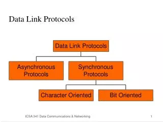
1. Data Link Protocols Asynchronous Protocols
Synchronous Protocols
Character-Oriented Protocols
Bit-Oriented Protocols
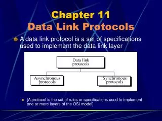
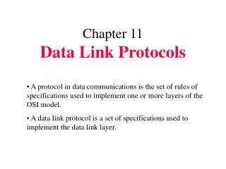
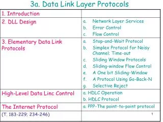
2. DATA LINK PROTOCOLS DLP are sets of specification used to implement the data link layer.
To this end, they contain rules for line discipline, flow control, and error handling, among others.
5. Asynchronous protocols A number of AP have been developed. See fig 11.2
These protocol are employed mainly in modems.
Has been replaced by synchronous protocol due to its slowness (start and stop bit)
Adv. Not complex and inexpensive to implement.
6. XMODEM Develop in 1979 for telephone-line communication between PCs. (FTP)
The first field is a one-byte SOH. The second field is a two-byte header.
The first header byte, the sequence number, carries the frame number. The second header byte is used to check the validity of the sequence number.
The fixed data field holds 128 bytes of data. The last field, CRC, checks for errors in the data field only. See fig. 11.3
8. YMODEM Protocol similar to XMODEM, with the following major differences:
The data unit is 1024 bytes
Two CANs are sent to abort a transmission
ITU-CRC-16 is used for error checking.
Multiple files can be sent simultaneouly.
9. Other Asynchronous Protocol Zmodem-newer protocol combination of xmodem and ymodem
BLAST-blocked asynchronous transmisstion is more powerful than XMODEM. Full-duplex with sliding window flow control.
Allows the transfer of data and binary files
Kermit is currently the most widely used asynchronous protocol.
The file transfer protocol is similar to XMODEM but much more powerful. Designed at columbia university.
See for details http://www.columbia.edu/kermit/
10. Synchronous protocols Better choice due to its speed. Used for LAN, MAN and WAN technology. Can be divided into 2 classes fig. 11.4
Bit-oriented protocols
The frame or packet is interpreted as a series of bits.
Character-oriented protocols(byte �oriented protocols)
The frame or packet is interpreted as a series of characters
All control info is in the form of an existing character encoding system. E.g. ASCII.
11. Character-oriented protocols (COP) Not as efficient as bit-oriented protocols.
Not widely used now. Consider obsolete
But easy to comprehend.
As foundation to understand bit-oriented protocols
In all DLP, control information is inserted into the data stream as separate control frames or as additions to existing data frames.
In COP, this info is in the form of code words taken from existing character sets such as ASCII. These multibit characters carry info about line discipline, fc, and error control.
Best known COP is binary synchronous communication (BSC) developed by IBM.
13. Binary synchronous communication (BSC) BSC was developed in 1964.
Usable in PPP and multipoint configurations.
It support half-duplex transmission using stop-and-wait ARQ flow control and error correction.
BSC doesn�t support full-duplex transmission or sliding window protocol.
Table 11.1 is a list of standard control characters used in BSC frame.
15. BSC Frames The BSC protocol divides a transmission into frames.
If a frame is used strictly for control purposes, it is called control frame.
Control frames are used to exchange info between comm devices. E.g. connection oriented.
If a frame contains part or all of the message data itself, it is called a data frame.
Data frames are used to transmit info, but may also contain ctrl info applicable to that information. See fig 11.5 for brief.
17. Simple data frame Refer fig 11.6. The arrow shows the direction of transm.
Begins with 2 or more SYN char which alert the receiver to the arrival of a new frame and provide a bit pattern used by the receiving device to synchronize its timing with that of the sending device.
STX start of text character. End of the control info. And the next byte will be data.
Data or text can consist of varying number of characters
An end of text (ETX) indicates the transition between text and more control characters
Finally one or two characters called the block check count BCC are included for error detection.
19. Frame with header Usually header will be added to include the address of the receiving device, the address of the sending device and the identifying number of the frame (0 or 1) for stop and wait ARQ.
This info is included in a special field called a header, which begins with a SOH character.
The header comes after the SYNs and b4 the STX character.
Refer fig. 11.7
21. Multiblock frames To minimize error, text in a messgae is often divided between several blocks.
Each block, except the last one, starts with an STX char and ends with an intermediate text block (ITB).
The last block start with an STX but ends with an ETX.
Immediately after each ITB or ETX is a BCC field.
In that way, the receiver can check each block separately for errors, thereby increasing the likelihood of detection.
If any block contains an error, however, the entire frame must be retransmitted.
23. Multiframe transmission Some messages, may be too long to fit into the format of a single frame.
In such cases, the sender can split the message not only among blocks but among frames.
Several frames can carry continuation of a single message.
To let the receiver know that the end of the frame is not the end of transmission, the ETB character in all frames but the last one is replaced by end of transmission (ETX).
The receiver must acknowledge each frame separately but cannot take over control of the link until it sees the ETX in the last frame. (See fig. 11.9)
25. Control frame A control frame is used by one device to send commands to, or solicit info from, another device.
A control frame contains control char but no data; it carries info specific to the functioning of the data link layer itself. See fig. 11.10.
Control frame serve 3 purposes: establishing connection, maintaining flow and error control during data transmission and terminating connections see fig 11.11
30. Data transparency problem in COP E.g. a receiver seeing the bit pattern 0000011 in data and reads it as an ETX char (ctrl char).
Data transparency in BSC is achieved by a process called byte stuffing.
It involves two activities
Defining the transparent text region with the data link escape (DLE) characters and preceding any DLE character within the transparent region by an extra DLE.
To define the transparent region, we insert one DLE char b4 the STX char at the beginning of the txt field and another just b4 the ETX.
31. Cont�
The first DLE tells the receiver that the text may contain control characters and to ignore them.
The last DLE tells the receiver that the transparent region has ended.
Problems may still arise if the transparent region contains a DLE char as text. In that case, we insert an additional DLE just b4 each DLE within the text.
See fig 11.12.