Download
1 / 3
30 likes | 137 Views
Testing and evaluation of EMCO's prototype boards for HV control and PMT HV base, including expected deliverables and specifications. Detailed instructions and diagrams provided for testing procedures.

E N D
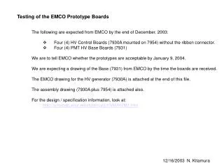
Testing of the EMCO Prototype Boards • The following are expected from EMCO by the end of December, 2003: • Four (4) HV Control Boards (7930A mounted on 7954) without the ribbon connector. • Four (4) PMT HV Base Boards (7931) We are to tell EMCO whether the prototypes are acceptable by January 9, 2004. We are expecting a drawing of the Base (7931) from EMCO by the time the boards are received. The EMCO drawing for the HV generator (7930A) is attached at the end of this file. The assembly drawing (7930A plus 7954) is attached also. For the design / specification information, look at: • http://amanda.wisc.edu/kitamura/HVM/HVM1.htm 12/16/2003 N. Kitamura
Tests Verify if the board mounting holes are correct, and the cable lengths are okay (in the DOM). HV Control Board The boards will be delivered without the ribbon connector. The boards will have a footprint for a 24 pin connector. Attach a 20-pin connector to this footprint (see the figure next page). Electrical Total power consumption Digital functions HV_DISABLE HV_ONOFF HV_ID DAC writes ADC reads HV Output HV (measure) PMT Base Board Total bleeder resistance (measure) PMT pulse measurement with a scope (Use a PMT socket and the cable adapter box. Set this up inside the dark box.) 12/16/2003 N. Kitamura
Pin #1 Component Side View Install 20-pin connector for these signals. Board edge DGND 21 22 DGND HV_DISABLE 23 24 HV_DISABLE “HV_DISABLE” is a 3.3V positive high logic (HV is disabled when connected to +3.3V). +3.3V is available in the DOMMB-Flasher Board connector. 12/16/2003 N. Kitamura