Integration and Overview of the CLAS12 Central Detector System
270 likes | 424 Views
This document presents a comprehensive overview of the CLAS12 Central Detector system, detailing its major components and integration methods. Key elements include the solenoid, support structures, and various detectors such as the Central Time-of-Flight (CTOF) and the High Threshold Cerenkov Counter (HTCC). It discusses the design considerations related to mounting, magnetic shielding, and environmental factors impacting detector performance. The document summarizes the integration strategy, installation procedures, and outlines future upgrades for enhanced capabilities.

Integration and Overview of the CLAS12 Central Detector System
E N D
Presentation Transcript
CLAS12 Central DetectorOverview and Integration David Kashy Hall B Lead Engineer CLAS CD Workshop Saclay December 2-3, 2009
Outline System Overview Solenoid and Support HTCC and Moeller Shields CTOF and Support SVT and support Summary/Conclusion
Hall B Overview Hall B – 98’ Diameter 20 Ton Polar Crane Cryogenic Supply and Return Line Beam dump tunnel Beam entry tunnel Hall B Space Frame
CLAS12 Detectors 3 Panels of Time of Flight – 1a & 2 reused from CLAS 3 Regions of Drift Chambers Low Threshold Cerenkov – Reused from CLAS Torus High Threshold Cerenkov Solenoid Pre-Shower Calorimeter Central Time of Flight Electromagnetic Calorimeter – Reused from CLAS Silicon Vertex Tracker
Solenoid Solenoid Lead can and Cryo reservoir Magnet Cryostat • Purposes are: • Central field for tracking • Provide magnetic shielding of Moeller Electrons • Peak field 5T • Homogeneous central region 1e-4 in Ø =25mm L = 40mm • Limited fringe field at locations of High Threshold Cerenkov PMT’s • Contract awarded to Wang NMR 11/20/2009 • Solenoid supported by 3 legged cart.
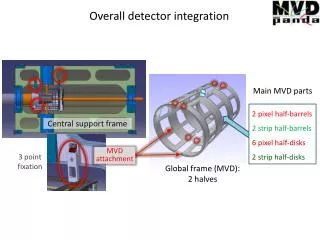
Central Detectors • Central tracker and Time-of-Flight detectors are attached directly to the solenoid. This provides stable reliable support that will limit external vibrations since its mass is very large ~20tonn
Plans for Mounting to Solenoid • Solenoid specification shows desired mounting to be at ends of magnet. • Details will need to be worked out with Vendor • CTOF will be mounted from both ends • Central Tracking Detectors must be mounted from upstream end only or we will loose HTCC and CLAS12 acceptance SVT Mounts CTOF Mounts Solenoid attachment to cart
High Threshold Cerenkov Counter High Threshold Cerenkov Outer cone- very close to light guides • HTCC surrounds the solenoid and CD from outside • It also protrudes inside with close clearance to the CTOF and also FST or other central tracker • Several Moeller Electron Shields are planned • They are envisioned to be cantilevered off the Torus • Materials to be Lead or Tungsten or a combination • Different configurations depending on the type of run (rastered or normal beam)
Central Detector Section View High Threshold Cerenkov Outer cone- very close to light guides Moeller Shield • CTOF • ID = 500mm • OD = 563 mm • HTCC starts at 380mm (desired to start earlier) • Moeller Shield fits very closely to inside cone of HTCC
Solenoid and Central Tracker SVT/Central Tracker supported off the Solenoid upstream Flange 6 link support system is the current design
Latest Central Tracker Layout Two size BST stave assemblies Target size limited to 3” OD Considering removable R1 BST to allow HD Ice target Max radius of Central Tracker 238mm Note the HTCC starts at 380 mm so there is some room for Micro Megas
Silicon Vertex Tracker • Cooling analysis shows efficient heat removal • Deflection analysis complete • Assembly and alignment methods will be confirmed with region 1 barrel assembly • Documentation and tech notes at http://clasweb.jlab.org/wiki/index.php/CLAS12_SVT Cold plate with brass inserts Stave support Stave
Latest Stave Design • Many designs considered • Latest design uses Silicon Wafer as structure as well as detector, (proposed by M. Merkin and analyzed by S. Mandal) • Prototype cores formed at JLab in mold • First results give core thickness 2.78mm +/- 0.015mm, with higher quality mold we expect better Copper/Aluminum Nitride FR4 Silicon 3 places Copper FR4 Rohacell
SVT Engineering Results • R2 BST thermal analysis • R3&R4 BST deflectionanalysis Max. Temp ~22.1 C Max. Deflection ~10.5m
CTOF There have been two parallel design efforts One with standard PMT’s and one with high magnetic field PMT’s decision on which one is pending more study on HF PMT design
Solenoid and CTOF • CTOF is supportedfrom both the upstream and downstream flanges of the solenoid • Room for Central calorimeter or Neutron detector is being left for future upgrade
Installation of Counter Assembly • Reference (conservative) design shown here • Counters will be built and tested complete • Light guides glued to scintillator • Wrapped and light sealed • PMT’s and 2 of the 3 layers of shield pre-installed • Individual counter assemblies will be installed one at a time • A strong-back will support the counters to prevent bending and glue joint failure • Installation fixture will clock the light guide assembly to the proper Φ angle Counter exploded view Strong Back
Counter Assembly Installed • Installation fixture will roll counter assembly into position through the Solenoid bore • Light guide assembly will be mounted to permanent clamps, then strong-back clamps can be removed
Beam Line Shielding Tagger Magnet and other Photon Devices BPM’s (2) Raster Magnets (2 pairs) Cryogenic Target and Cart • Most Beam Line Devices reused from CLAS • Steering , focusing and raster magnets • Beam Profile Monitors and Beam Position Monitors • Cryogenic Target • Photon Devices will be left on beam line including Photon Tagger, radiators, collimators and pair spectrometer • Shielding after target simulated and defined through the Torus • Re-arrangement of Moeller measurement system components, a study optimizing this is underway
Hall B Prepared for CLAS12 Installation Forward Carriage with Electromagnetic Calorimeters Space Frame Cleared of Beam Line equipment
CD installation An additional level will be added to the space frame for the CD and HTCC Torus will be installed next The Solenoid will be craned in CTOF will be installed after solenoid acceptance testing Central Tracker is installed last
Torus Assembled and Central Detector added Solenoid and Central Detector - slides on rails into the space frame for maintenance Torus positioned and aligned Space frame addition for Central Detector and HTCC
Safety To work in Hall B all persons must be Trained and Qualified All work in Hall B work is scheduled and reviewed by the Hall Work Coordinator Independent activities have been and will continue to be reviewed for space and resource interferences Stop Work Program will always apply ISM principles must be followed Lock Tag and Try/LOTO will be used Tested and Inspected lifting fixtures PPE will be worn as required Hall B is a low radiation environment this will allow most items to be removed from the hall after survey w/o delay.
Summary Design of CTOF and SVT proceeding Will be working with Solenoid vendor on supports for CD Looking forward to contributions on Central Detector Planning for installation being integrated in the design phase