1. Introduction
1. Introduction. Textbooks and References. K. K. Sharma, “Optics: Principles and Applications,” Academic Press. E. Hecht: “Optics,” Addison Wesley. L. Setian, “Applications in Electro-Optics,” Prentice Hall. R. G. Hunsperger, “ Integrated Optics: Theory and Technology,” Springer.

1. Introduction
E N D
Presentation Transcript
Textbooks and References • K. K. Sharma, “Optics: Principles and Applications,” Academic Press. • E. Hecht: “Optics,” Addison Wesley. • L. Setian, “Applications in Electro-Optics,” Prentice Hall. • R. G. Hunsperger, “ Integrated Optics: Theory and Technology,” Springer. • F. T. S. Yu and X. Yang, “Introduction to Optical Engineering,” Cambridge Univ. Press. • E. Uiga, “Optoelectronics, “Prentice Hall. • F. G. Smith and T. A. King, “Optics and Photonics: An Introduction,” Prentice Hall. • Wikipedia
Propagation of Light Velocity of light : permeability of medium : permittivity of medium c: velocity of light in a vacuum n: refractive index of medium Reflection and refraction Law of reflection: 1 = Law of refraction: n1sin 1 = n2sin 2 (Snell’s law) Fermat’s Principle: the path taken between two points by a ray of light is the path that can be traversed in the least time.
Refractive Index • Velocity of light in medium with refractive index n: v=c/n=fλ where f, λ,and c are the frequency, the wavelength, the vacuum velocity of light, respectively. • Refractive index is not a constant. It depends on the frequency (wavelength), the polarization of light (direction of E-field), etc. • Some materials are birefringence crystals (two refractive indices, ne and no, for two orthogonal polarizations).
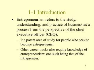
Total Reflection Left: top view of LED with no water Right: top view of LED under water
Opaque and TransparentMaterials • Opaque nonmetal : Nonmetal objects that do not allow any light to pass through. • Opaque metal : Metals that do not allow any light to pass through – Aluminum pan, chrome faucet, … • Transparent material : Objects allow much of the light from light source to pass through – A glass window, water, … • Translucent material : Objects that allow some light to pass through – A single sheet of paper, orange juice, …
Bouguer-Lamber’s Law • Bouguer-Lamber’s law : T=I/I0=exp(-αl), where T is the transmittance, I0 is the incident radiance, I is the transmitted radiance, α is the absorption coefficient of the material, and l is the thickness (path length).
Colorimetry • Colorimetry is the science and technology used to quantify and describe physically the human color perception. • Colorimetric equipment: 1. A tristimulus colorimeter measures the tristimulus values of a color. 2. A spectroradiometer measures the absolute spectral radiance (intensity) or irradiance of a light source. 3. A spectrophotometer measures the spectral reflectance, transmittance, or relative irradiance of a color sample. 4. A spectrocolorimeter is a spectrophotometer that can calculate tristimulus values. 5. A densitometer measures the degree of light passing through or reflected by a subject. 6. A color temperaturemeter measures the color temperature of an incident illuminant.
RGB Color Model and Color Addition • Red(R), green (G), and blue(B) are primary colors of light. • The RGB color model is an additive color model. • A computer monitor mixes composition of RGB to create color pictures. R-redG-greenB-blueC-cyanM-magentaY-yellow W-white
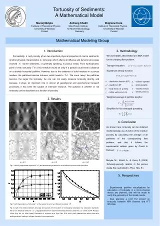
Pure inks/paints/pigments absorb a single frequency or color of light. The color of light absorbed by a pigment is merely the complementary color of that pigment. Magenta ink/paints/pigments absorb green light and green paints/pigments absorb magenta light (Green and magenta are the complementary colors to each other). Cyan ink/paints/pigments absorb red light and red paints/pigments absorb cyan light (Red and cyan are the complementary colors to each other). Yellow ink/paints/pigments absorb blue light and blue paints/pigments absorb yellow light (Blue and yellow are the complementary colors to each other). Inks/Paints/Pigments and Complementary Colors Two spectral reflectance curves. The objects reflect lights with shorter wavelengths while absorbing those in others, lending them blue appearances.
CMY/CMYK Color ModelandColor Subtraction • Cyan (C), magenta (M), yellow (Y), and key (K, black) are used in mixing paints or color printing. • The CMY/CMYK color model is a subtractive color model. • Eg1. C+M=(W-R)+(W-G)=W-R-G=(R+G+B)-R-G=B • Eg2. Y+C=(W-B)+(W-R)=W-B-R=(R+G+B)-B-R=G
Questions about Color Addition/Subtraction • White paper does not absorb any colors. R+G+B-nothing=R+G+B=white, so the paper appears white. • White paper does not absorb any colors. R+G-nothing = R+G = Y, so the paper appears yellow. • White paper does not absorb any colors. G+B-nothing=G+B=C, so the paper appears cyan. • Red paper absorbs cyan light; R+G+B–(G+B) =R, so the paper appears red. • Red paper absorbs cyan light; G is absorbed (B would be absorbed if it were present). R+G-G =R, so the paper appears red. • Red paper absorbs cyan light. B+G–(B+G)= nothing, so the paper appears black. • Yellow paper absorbs blue; R+G+B-B=R+G = Y., so the paper appears yellow. • Yellow paper absorbs blue light, but there is no B in the incident light. Thus nothing gets absorbed. R+G-nothing=R+G=Y, so the paper appears yellow. • Yellow paper absorbs blue. G+B-B=G, so the paper appears green.
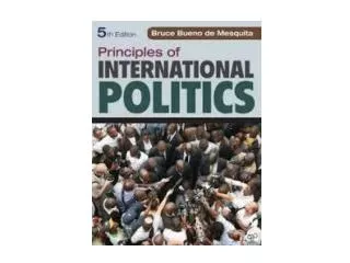
Brightness and Lightness Decreasing brightness with depth (underwater photo as example • Brightness: Perceptional luminance of a visual target. • Lightness: The Munsell color model of lightness: a color with a low value is nearly black.
Colorfulness, Chroma, and Saturation • Colorfulness: The degree of difference between a color and gray. • Chroma: • Saturation:
Contrast • The contrast is the ratio of white brightness and black brightness. If we make the white parts become brighter and the black parts become darker, the image looks sharper. A good LCD TV requires 800:1 at least.
Metamerism (異譜同色) • Two light sources made up of different mixtures of various wavelengths but appear to be the same color; this effect is called metamerism. • The concept of color can be divided into two parts: brightness and chromaticity. For example, white is a bright color but grey is considered to be a less bright version of that same white. In other words, the chromaticity of white and grey are the same while their brightness differs.
Hue(色相) Encodings of RGB • A visual sensation similar to one of the primary colors, or a combination of two of them. • In painting color theory, a hue refers to a pure color—one without tint or shade (added white or black pigment, respectively).
Human Vision Color sensitivity Human eye C.I.E. Standard observer
Human Eye-Similar to a Camera Cornea and lens: the two lens system. Iris: like diaphragms (快門,光圈) or stop in a camera. Pupil: camera aperture. Retina: at the back of eyeball, like the film
S, M, and L Cells inHuman Eye • Rod cells are sensitive to brightness/luminance, saturated at daytime, for peripheral and night vision (scotopic vision), combined maximum sensitivity peak 550 nm. – Mostly distributed away from fovea. • Cone cells have 3 types : – S (short wavelength): blue sensitive (peak at 445 nm) – M (medium wavelength): yellow or green sensitive (peak at 535nm) – L (long wavelength): red sensitive (peak at 575nm) – Mostly distributed at the fovea. • S: M: L cell count ratio = 1: 20: 40 ⇒ human’s eyes are much more sensitive to red than blue.
RGB Tristimulus Values Given these scaled color matching functions, the RGB tristimulus values for a color with a spectral power distribution would then be given by
CIE 1931 Chromaticity Diagram • The CIE 1931 xy chromaticity space, which shows the chromaticities of black-body light sources of various temperatures, and lines of constant correlated color temperature • X is roughly red, which is a linear combination of cone response curves chosen to be nonnegative. • Y means luminance. • Z is quasi-equal to blue stimulation (or the S cone response). CIE (Commission Internationale de l'Eclairage) — the International Commission on Illumination
Color Temperature • The color temperature of a light source is the temperature of an ideal black body radiator that radiates light of comparable hue to that of the light source. • Higher color temperatures over 5000 K are called cool colors (blueish white), but the lower color temperatures (2,700–3,000 K) are called warm colors (yellowish white through red).
CIE Standard Illuminants • A: A tungsten light source with correlated color temperature of about 2,856 K producing a yellowish-red light. • C: A tungsten light source coupled with a liquid filter to simulate indirect sunlight with a correlated color temperature of 6,774 K. (Obsolete) • D (Daylight illuminants): Standard illuminant D65 is nearly identical to standard illuminant C except that it is a better simulation of indirect sunlight as it includes an ultraviolet component for better evaluation of fluorescent colors. D50 and D75 correspond to color temperatures of 5,000 K and 7,500 K, respectively.
CIE Standard Illuminants (Cont’) • B: An illuminant having relative spectral power distribution near to that of a direct sunlight with a correlated color temperature of 4874 K. (Obsolete) • E: The equal-energy illuminant is of mathematical utility. It is defined with a relative spectral power of 100.0 at all wavelengths. • F: Various types of fluorescent lamps including cool-white fluorescent F2 (CCT of 4,230 K, Obsolete), daylight fluorescent F7 (CCT of 6,500 K → D65), F8 (CCT of 5,000 K→ D50), and triband fluorescent F11 (CCT of 4,000 K).
Dispersion by Prism The refractive index n is the function of wavelength (frequency); therefore, the light rays with distinct wavelengths have different refractive angles and velocities.
Rainbow The primary rainbow is easy to observe. It results from a single internal reflection and two refraction of the light ray in water drops. The index of refraction of water depends on the wavelength. Under good conditions, a secondary rainbow can also be observed. In this case, two internal reflections of light within the water drops occur. The intensity of the secondary rainbow is much lower than for the primary or main rainbow.
Diffractions by Apertures/Sharp Edges Diffraction — light path deviates from an initial propagation
Diffractions by Gratings Grating: Periodical structure in optical component/device/equipment/system
Reflection/Scattering by Grating • Consider a light ray traveling to the right in the corrugated waveguide (grating). The period of the grating structure is Λ. The ray scattered by the teeth fulfill sinθ=(mλ/Λng)-1, where m is an integer. • Special case 1: Ray scattered in the forward direction if m=0 • Special case 2: Ray scattered in the direction normal to the surface if m=1 and Λ=λ/ng • Special case 3: Ray scattered in the backward direction if m=2 and Λ=λ/ng. It is an optical reflection by the grating.