Download
1 / 26
280 likes | 413 Views
Protocol Architectures for Satellite ATM Broadband Networks. Content. Introduction Short overview of ATM (Asynchronous Transfer Mode) ATM cell encapsulation (Data Link Control) S-ATM protocol Comparrison between Partial Packet Discard (PPD) and Data Link Control (DLC).

E N D
Content • Introduction • Short overview of ATM (Asynchronous Transfer Mode) • ATM cell encapsulation (Data Link Control) • S-ATM protocol • Comparrison between Partial Packet Discard (PPD) and Data Link Control (DLC)
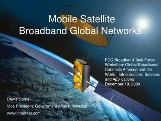
1. Reasons for using ATM • ATM networks can rapidly and economically extend boundaries of any terrestrial network • To provide coverage to remote ATM users • The demand for satellite communication at the Ka frequency bands (20/30 GHz) increased
Aim To bring the ATM functionality closer to the user terminal, without violating its connection-oriented nature and guarantee similar quality of service (QoS) characteristics
Entities in a satellite network (1) • Satellite Adaption Unit (SAU) Non standard, specially designed unit to provide User Terminals access to the satellite network. It performs all necessary protocol adaption of the User Terminals (UT). Includes all physical layer functionalities. • Gateway Stations (GTW) Land Earth stations that provide connectivity to external networks
Entities in a satellite network (2) • Network Control Station (NCS) Central entity used in GEO satellite system that provides overall control of satellite network resources and operations. Is responsible for call routing, call managment, authentication, billing, registration and deregestration. Usually one NCS per GEO satellite.
2. Overview of ATM • Main use as transport technique and in core networks • Connection-orientet • Multiplexing is possible • Cells of fixed length (53 byte) • Transfer rates from 155 Mbps to 1.2 Gbps
3. ATM cell encapsulation(Data Link Control protocol) Advantages: • Very simple and easy to implement technique for passing arbitrary information through network entities • Supports different user terminal standards through a satellite specific interface
Data Link Control • Satellite specific LLC (Logical Link Control) and MAC (Media Access Control) grouped together in the DLC (Data Link Control) protocol • DLC is necessary to transfer information between the satellite network entities across the air interface
Dimensioning the SCI field • Length of the SCI (Satellite Connection Identifier) field needs to be large enough to include the maximum number of all active connections that can be supported at any time
LLC / CRC / RRM field • The LLC (Logical link Control) field can be used to multiplex uplink connections coming from the same SAU using the same SCI value • The CRC (Cyclic Redundancey Check) field is required to detect errors in the satellite packet header • The presence of the RRM (Radio Resource Managment) field depends on the selection of the resource managemant protocol
Additional overhead • 2 Bytes for the SCI field (including 2-3 Bits for the RRM field) • 3 Bytes for the LLC field • 1 Byte for Error Correction 6 Bytes additional overhead
Conclusion Minimum processing power at the SAU and GTW stations is needed BUT: 6 bytes additional overhead on every cell (11 bytes including the ATM header)
4. S-ATM protocol • Uses a modified ATM header • ATM header extraction at the SAU • ATM header reconstruction at the GTW • Combines the function of MAC and ATM
S-ATM header structure • The standard VPI/VCI ATM fields are replaced by the satellite VPI/VCI (SVPI/SVCI) fields, which are used by the satellite onboard switch • CLP field is the same as in the ATM header • Header length is 5 Bytes (like the normal ATM-header)
Protocol stack architecture • No use of the LLC layer in this system because ATM already offers multiplexing capability • Not enough place in the header for a LLC field Use of PPD (Partial Packet Discard)
Partial Packet Discard (PPD) • Mechanism to detect erroneous cells at the satellite switch • End user is responsible for acknoledgement and retransmission of higher layer PDUs • Erroneous cells and consecutive cells that belong to the same PDU get deleted • No additional processing power is needed
Conclusion No additional overhead for the ATM cells BUT Extra processing power is needed to modify the ATM header
5. Comparison between PPD and DLC Calculation of the radio link throughput (in packets / packet transmission time) • PER = 1 – (1 – BER)length • Radio link throughput = (1 – PER) [p/(p+h)] BER = Bit Error Rate PER = Packet Error Rate length = length of a higher layer PDU (in bits) p = payload h = header length