Download

1 / 21
210 likes | 332 Views
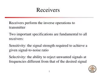
BEST 2 RECEIVERS. Jader Monari j.monari@ira.inaf.it IRA -INAF- Bologna –Italy-. The Best-2 platform is composed by 32 receivers 8 cylinders and offers about 1440 m 2 of collecting area.

E N D
BEST 2 RECEIVERS Jader Monari j.monari@ira.inaf.it IRA -INAF- Bologna –Italy-
The Best-2 platform is composed by 32 receivers 8 cylinders and offers about 1440 m2 of collecting area. It is primarily aimed to test adaptive beamforming, calibration techniques, RFIs algorithms and develop / test some crucial technology. 1 2 8
BEST-x GENERAL ARCHITECTURE
Activedevice OIP3>32dBm P1dB>16dBm NF<0.2dB
Balanced Architecture • A1=A2 • Hybrids good phase and amplitude match • NFA1=NFA2 reduction (NF = ILInput_Hybrid+NFA)
Balanced LNA, theprototype S22 S21 NF<0.5 between 380MHz and 450MHz OIP3 > + 34dBm between 350 e 450 MHz
RFin Inside the FE RFout NF=0.45dB Tn=32K Gain=60dB BW=16MHz@408MHz OIP3>+33dBm Input RL>15dB Output RL>15dB Power Supply=10-15Volt@=245mA
Mechanicalassemblyof FE 3 stages FE Dischargesprotectioncircuit Opt. TX
IF Receiver specifications • IP3 spurs product -10dB lower than the system thermal noise (KTB) IIP3 > -60dBm • Auxiliary 408MHz out as monitor • IF=30MHz, OL=378MHz • Pin_ADCBW=-35/-30dBm @16MHz (ADC Berkeley) • PinKTB=-107dBm (Tb=20K) /-100dBm (Tb=500K) GSYSTEM=70dB GRX=35dB • Digital controlled attenuator (31.5dB with 0.5dB step) for match the gain of the different receivers and to have the right dynamic range at the ADC section • Only an MMIC model for all the receiver parts (1 RF, 1 OL and 4 IF)
“Carrier” Board • Powermonitor (AD8362) AD10dB • Controlofswitch on-off eachamplifier (diagnostic and power-safevia software) uP IF
Inside the IF receiver…. To A/D Signal paths: RF, IF, OL and digital control&monitor.
Two N-S CylindersofCarrier-RXO 485 bus 19” To LAN
Syntethizerfor clock 8X Receivers PPS generator 8X LO distributor Clock Distributor 8X Receivers In the back 16X PPS distributor 8X LO distributor IBOB/ADC 8X Receivers 12X InfiniBandSwitch 8X LO distributor BEE2 8X Receivers 8X LO distributor 4X LO distributor IBOB/ADC Powersupplies Switch Ethernet 100BT
Conclusions • Receivers, analogue optical links and data aquisition for BEST-2 are already installed and under test and programming 2) Future work will be to design and develop a new IF to sample directly the 408MHz 3) New mechanical chassis for next generation FE are going to use to simplify test and assembly 4) New digital uC is going to be used in order to monitor temperatures and eventually to control NGs or heaters/peltier to stabilize the FE environment