Download
1 / 13
140 likes | 355 Views
ECG Signal Quality Measurement. Client: Alan Clapp - Senior Electrical Engineer, GE Medical Systems Advisor: John G. Webster, Ph. D Group Members: Paul Anheier, Michael Piché, John Puccinelli, Scott Wiese. Problem Statement:.

E N D
ECG Signal Quality Measurement Client: Alan Clapp - Senior Electrical Engineer, GE Medical Systems Advisor: John G. Webster, Ph. D Group Members: Paul Anheier, Michael Piché, John Puccinelli, Scott Wiese
Problem Statement: • Although modern ECGs sufficiently eliminate many types of interference, more optimization is possible and necessary. The focus of the project, therefore, is to further improve signal quality and develop a reliable alert system to detect signal degradation whether through procedural guidelines and/or hardware modifications.
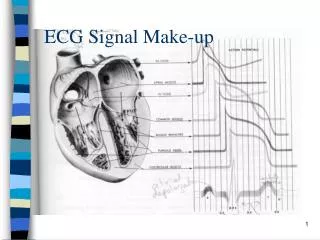
Background • Poor ECG signals can have many causes: • Electrical interference from other instruments/power lines/lights • Improper electrode placement • Poor electrode adhesion • Electrode aging/degradation • Most common causes occur at the skin/electrode interface • Poor contact or old electrodes result in high impedance at the skin/electrode interface • This results in a degradation of signal amplitude and an increased susceptibility to motion artifact
Background • What is deemed “good” signal quality is highly subjective • It is impractical to determine a universally acceptable signal quality due to subjectivity • Solution?...
Proposed Solution • Include as a feature on future electrocardiographs a graphical display of measured skin impedance over time • Graph would have fixed scale to make interpretation easier • Clinicians could make their own decisions on signal quality based on trends in the graph
Requirements for Implementation • We must determine a suitable scale to use for graph of skin resistance • Determination of the best carrier signal to measure impedance (DC, ~.2 Hz, 250 Hz) • Determine impedance level above which problems frequently occur • Determination a typical response of skin impedance over a long time interval (24 hours)
Carrier Signal Testing • Goal: Identify most reliable/accurate carrier signal for measuring impedance. • Skin is not perfect resistor, must determine behavior at different frequencies • Candidates (at request of GE engineers) • DC • 250 Hz • .2 Hz
Carrier Signal Testing • Human Subjects Committee has conditionally approved public participants. • With this approval, we can maximize test subject diversity • ↑ subjects = ↑ skin types = more realistic results • Considerations for Analysis • Input impedance of oscilloscope • Skin resistance changes over time
Skin Impedance Testing • Goal: Collect data over 24 hours of impedance change at skin-resistor interface. Use to establish a scale. • Study is to include multiple types of electrodes. • Necessary for implementation of a graphical display of skin impedance change versus time.
Future Directions • Complete carrier signal testing and analysis. • Establish resistance scale. • Develop layout of graphical display. • Characterize quality/response of various electrodes. • Submit to GE for review and possible implementation. • Publish the findings.
Conclusions • Graphical representation of skin impedance will provide useful data and help make decisions on signal/electrode quality • Determining a signal carrier is a key component of representing resistance changes.