Download
1 / 24
320 likes | 565 Views
Explore the application of Particle Image Velocimetry (PIV) for flow pattern characterization, with insights into typical experimental setups, use of seeding particles, advantages and disadvantages of PIV, and comparison with other measurement techniques like Electrical Capacitance Tomography (ECT). Learn about the components and mechanisms of single plane and twin plane ECT systems, as well as the PIV system setup and stability analysis. Gain an understanding of the dynamics of particulate systems through the Particle Doppler Particle Analyzer (PDPA) and other methodologies like Discrete Element Method (DEM) for simulating particle motion in various flow patterns. Discover key flow types, electrostatic characterizations, stability diagrams, and models for analyzing forces in different flow scenarios.

E N D
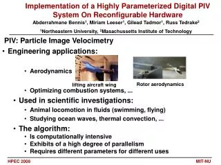
Application of Particle Image Velocimetry (PIV) for flow pattern characterization
Typical Experimental setup Apparatus includes: CCD camera, Laser, light sheet, mirror, lenses, synchronizer, computer, flow column, seeding particles
Use of seeding particles Typical size range: 10 – 100 mm Acts as tracer particles to observe fluid flow density as close to the working fluid such as water Small enough to follow the fluid motion Big enough to be captured by CCD camera good reflectivity Chemically inert / does not dissolve in fluid
Advantages of PIV • High degree of accuracy • Entire velocity field can be calculated • Capable of measuring velocity in 3 dimensions Disadvantages of PIV • Seeding particles have to be carefully selected • Size of flow structures limited by image resolution • Costly
Measurement Techniques • Electrical Capacitance Tomography (ECT) • Velocity (Twin Plane) • Concentration • Particle Image Velocimetry (PIV) • Velocity • Phase Doppler Particle Analyzer (PDPA) • Number density
Single Plane ECT System Components Capacitance Measurement Data Acquisition Unit A/D Converter Capacitance To Voltage Transfer Multiplexing Circuit Insulating Pipe Control Signals Electrode Data Post Processing Image Reconstruction Algorithm
Single Plane ECT System • Mechanism • Measures capacitance of 12 electrodes • Obtains 66 capacitance values • Utilizes distribution of permeability to obtain porosity • Solves for solid concentration
Signal Delay ( D ) Cross Correlation U = L /D Twin Plane ECT System Plane 1 Plane 2 V
Twin Plane ECT System • Mechanism • Measures particulate concentration profiles at two axially-separated locations • Obtains velocity profile via correlation techniques • Obtains overall flow rate via integration of product of both concentration and velocity profiles • Obtains the volumetric flow of the particulates via second integration over a period of time
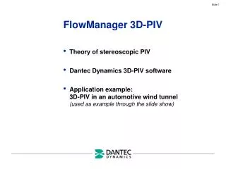
PIV System (1) Synchronizer (2) Computer (3) Laser generator (4) CCD camera (5) Vessel (6) Vibrator (7) Function generator (8) Power amplifier
PIV System • Mechanism • Measures instantaneous global velocity in a flowing fluid • CCD camera takes pictures • Displacement/Time = Velocity
Perturbation Form Perturbations: Where: And:
Ωr is > 0 (positive): amplitude of disturbance increases with time • Ωr is < 0 (negative): amplitude of disturbance decays with time • Ωr is positive: unstable mode • If you introduce a small disturbance, integrate forward with time, the variable will move away from steady state • Ωr is negative: stable mode
Stability Diagram (+ve Eigen value) (-ve Eigen value)
Electrostatic Characterization 5: MPCT / ECT 6: Induced current measurement 7: Faraday Cage
Types of flow • Disperse flow (highest u) • Half Ring flow • Ring flow (lowest u)
Summary • Air flow rate - lower air flow rate, higher induced current and particle charge density • Time – Charge accumulation for pipewall and individual particle increases with time for all types of flow. Leads to clustering of particles even in case of disperse flow. • Composition – Antistatic agent, Lacrostat 519 powder can reduce electrostatic effect. • Tribroelectrification – strong force effect created on walls when particles slide on pipe wall.
Discrete element method (DEM) A numerical method for computing the motion and effect of a large number of small particles in a pipe by using computational fluid dynamics. Outline of the method A DEM-simulation is started selecting a model and setting an initial gas velocity. The forces which act on each particle are computed from the initial data, relevant physical laws and contact models. The change in the position and the velocity of each particle during a certain time step can be computed from Newton's laws of motion.
Models • Force Displacement Model • Fluid Drag Force Model
Types of flows • Vertical pneumatic conveying • Dispersed flow • Plug flow • Horizontal pneumatic conveying • Stratified Flow • Moving dunes • Slug Flow • Homogeneous Flow For different types of flow and gas velocity, the solid flow rate profile and the solid concentration profile can be determined from the data and graph.