Download
1 / 23
240 likes | 403 Views
Old Telephone cabling. 4 wire RJ 11 Color code Used in commercial and residence NEW. Prior to Divestiture. In years gone past, it was the responsibility of the phone company not only to bring phone service to your house but to do the phone wiring within your house as well.

E N D
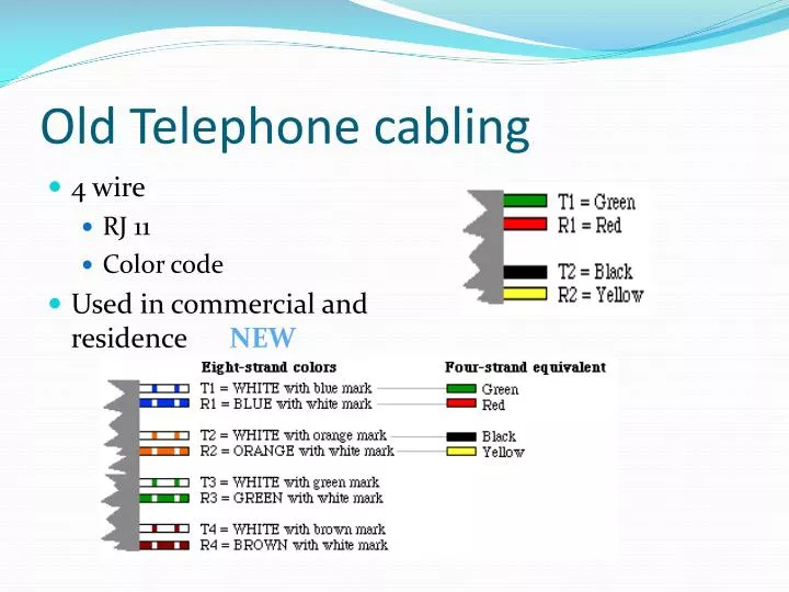
Old Telephone cabling • 4 wire • RJ 11 • Color code • Used in commercial and residence NEW
Prior to Divestiture • In years gone past, it was the responsibility of the phone company not only to bring phone service to your house but to do the phone wiring within your house as well. • This is no longer the case. When you order phone service to your house, the local phone company installs a network interface device, a sturdy grey plastic box usually mounted either in your basement or on an outside wall.
Residential • Before Divestiture • Phone company maintained • After • Demarc • You pay if the problem is on your premise • Statement by operator when calling in a trouble report “if the problem is internal you will need to cover the cost of the service call” • Note: Star and Branching
Commercial • Before divestiture • Teleco maintained all wiring • Teleco repaired the phones • After • internal wiring turned over for $1 • Phones given to the campus • Demarc established • Normally at the EF or Entrance Facility • FVTC – maintained on the 2nd floor
Commercial continued • Typical install • Large multi-conductor cable ran into Demarc • Ran into EF Entrance Facility • Backbone cables ran to TR’s Telecom Rooms or IC’s Intermediate Cross Connects • From TR’s to 110/66 blocks • 110/66 cross-connect field to 110/66 Distribution field • Distribution field to station jack or • Mutoas or connection points then to stations • IC’ to TR’s via a backbone cable
Jack to Rack • Primary focus will be on the cable that runs from the TR to the work area station jack. • Performance tests • cable termination • 110/66 blocks • Patch Panels
Equipment Racks • 19” Rack standard • 23” Rack standard
Grounding • Need • Power companies do not provide ground • Safety issues • BISCI Standards, Doc cam pg 292, 296
Typical facility layoutPG 9 BISCI – Doc cam STA • Draw on board IDF CO IDF MDF IDF IDF
Typical Residential layout Wire color code Telephone Network Interface • Draw on board
Plenum versus non plenum cabling • Why • Characteristics
Cable Specifications • Review specs on a given cable – look up on web • http://docs.commscope.com/Public/5504LC.pdf
NEXT – Near end cross talk or EMI, signal transmitted on an adjacent pair from the near end and measured at the near end • FEXT – Far end cross talk, signal transmitted on an adjacent pair from the near end and measured at the far end of the cable • AttenuationThis is the decrease in signal strength (expressed as negative dB) from one end of a cable to the other. The main causes of attenuation are impedance, temperature, skin effect and dielectric loss. Impedance is the combination of resistance, inductance and capacitance in a cable, it is measured in Ohms and opposes the flow of current.
DC loop resistanceThis is simply the resistance between the two conductors of a twisted pair which is looped back at the far end. The primary purpose of this test is to make sure that there are no high resistance connections in the link. • Return LossWhen a cable is manufactured there are slight imperfections in the copper. These imperfections all contribute to the Structural Return Loss (SRL) measurement because each one causes an impedance mismatch which adds to the cables attenuation. • DelayThis is the propagation delay or the time it takes for the signal to travel from one end of the cable to the other
Delay Skew The difference between the fastest and slowest pairs. Some networks use a four pair transmission method, this means that the signal is split into four, sent down the four pairs in the cable and re-combined at the far end. It is essential that the signals reach the far end at near enough the same time, otherwise the signal will not be re-combined correctly.
ACR • The pink area in the graph is the attenuation, and the blue area is the crosstalk.
ACRThe first thing to understand about testing data cables is the ACR, this stands for Attenuation to Crosstalk Ratio. The pink area in the graph is the attenuation, this can be caused by several things as will be explained below, and the blue area is the crosstalk. Attenuation is the reduction in signal strength over the length of the cable and frequency range
the crosstalk is the external noise that is introduced into the cable. So, if the two areas meet, the data signal will be lost because the crosstalk noise will be at the same level as the attenuated signal. • ACR is the most important result when testing a link because it represents the overall performance of the cable.
Toning out a cable Test Equipment Demo –click on image • Generator • Receiver
Basic Telephone service Signals on a telephone line Tracing a line, another set of test equipment • Battery • Ring • Dial tone