Download
1 / 30
300 likes | 440 Views
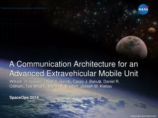
A Communication Architecture for an Advanced Extravehicular Mobile Unit. William .D. Ivancic , Obed S. Sands , Casey J. Bakul z , Daniel R. Oldham , Ted Wright, Martin A. Bradish , Joseph M. Klebau SpaceOps 2014. Presentation Outline. Background Objectives Terminology

E N D
A Communication Architecture for an AdvancedExtravehicular Mobile Unit William .D. Ivancic, ObedS. Sands, Casey J. Bakulz, Daniel R. Oldham, Ted Wright, Martin A. Bradish, Joseph M. Klebau SpaceOps2014
Presentation Outline • Background • Objectives • Terminology • Design Philosophy • Telemetry • AEMU Communication Architecture • Subsystems • Intersystem Communications • Summary / Conclusions • A Question to Ponder
Background • Extravehicular Mobility Unit (EMU) suits (space suits) are still using technology from the 1970's and 1980's, particularly regarding the communications system. • NASA is developing an Advanced Extravehicular Mobility Unit (AEMU) . • This is being performed within the Advanced EVA Systems Development Project under the Advanced Exploration Systems (AES) Program. • A key part of this development is the spacesuit Primary Life Support Subsystem (PLSS) • GRC's role is to develop a prototype suit avionics subsystem, the Power, Avionics and Software (PAS) subsystem and to research new technologies • The results will be used to refine requirements for the AEMU as well as to potentially integrate new technologies into the AEMU.
Terminology • Data Types • Application Specific (e.g., file transfers) • Event: a message type indicating change of state that may require some action. • Streaming: real-time streaming applications such as audio and video • Telemetry: system and subsystem status, configuration and measurements • Call Group (i.e. Voice Loop): A group of voice reception devices that all listen on a common “channel”. • Home: Where the crew members return to after their EVA (e.g. ISS, Habitat) • Multi-Homed Network: A node connected to two or more Wide Area Network (WAN) networks such that data has multiple potential paths in which it can flow through to it's final destination.
Communication Architecture Design Philosophy • The AEMU design is for use on ISS, Orion, future exploration missions (e.g., asteroid retrieval) and planetary exploration science terrestrial sorties. • Goal is to develop an flexible, extensible, testable, and cost effective architecture. • Readily enable infusion of new technology. • During Phase 1, PAS-1.0, the various Assemblies have been developed, for the most part, independently. • Allowed separation of safety criticality • Enabled research elements to to be developed on parallel paths without effecting safety critical assembly development • Allows assembly development to occur in a phased, evolutionary manner. • Investigate the applicability and use of existing software technologies and techniques • Learn from others • Both the army operations and the AEMU need separate call groups and multi-homed radio systems. The Soldier Radio Waveform project already has these capabilities. • The AEMU is also quite similar to Intelligent Transportation Services (ITS) vehicles with some systems being critical for safety of life and others being desired features.
Telemetry • Goal is to develop develop a flexible telemetry format that does not required predefined large fixed-fielddata structures to be sent with each transmission. • Only send the relevant telemetry that two subsystems need to communicate. • Investigate various Fixed ID/Data pairs such that each piece of telemetry is identified by a Flag indicating if the next field value is an ID or data. • The ID value would indicate what the data represents. • The data value would represent the value corresponding to the ID. • Decision to utilize Google Protocol Buffers (GPB) • It is a standardized format similar to what we were developing • Google's lingua franca for data with over 48,162 different message types defined in the Google code tree across 12,183 .proto files. • Open source code was available that generates source code for the protocol encoding and decoding tasks. • Protocol Buffers uses a key/value pair for each entry. Many of these key/value pairs utilize Variants, a variable length method of serializing integers using as little as one byte. • This method allows for very efficient bits-on-the-wire encoding.
Telemetry For PAS-1.0, the deployment, the only required key/value pairs are Timestamp , Sender (e.g, CWCS, Informatics, Audio, COMM) and Type . All other key/value pairs are optional (depending on the required Type field),
Messages / ZeroMQ • For PAS-1.0, concentrate on the Messages (what needs to be communicated between subsystems and AEMUs) rather than the Messaging implementation. • A Publish/Subscribe network architecture is a best practice for reliable information exchange between loosely coupled networked assemblies • Used Open Source ZeroMQmessaging library to avoid the complications of writing reliable publish/subscribe networking code. • Make coding a basic publish/subscribe system trivially easy • Does not require a separate daemon process or broker software • Can easily switch transport mechanisms as it can use different protocols depending on the peers location (TCP, Pragmatic General Multicast (PGM) multicast, InterprocessCommunication (IPC), inproc shared memory) • Extremely importantly for our code reuse.
Communication Architecture Soldier Radio Waveform HOME
Caution, Warning and Control System (CWCS) The CWCS is an engineering development prototype effort. Information obtained from this implementation effort will be use in developing requirements for future AEMUs. • Monitors consumable levels and critical life support system functions • Provides AEMU fault detection with both visual warning via messages on the text display and via EVENT messages send to the Audio system. • C&W detects when the AEMU’s operational configuration (aka X-state) has changed, based the configuration of switches and component settings, as well as when the ambient pressure has changed. • C&W monitors various parameters and performs checks during IV operations vs. EVA/vacuum operations. • C&W offers numerous automated sequences, such as a suit leak check and a prebreathe clock, based on the X-state. • C&W performs an automated AEMU checkout of all critical AEMU functions. • Intent is to screen for the same type of system failures that C&W monitors and checks during an EVA.
Audio Processing - Overview • The Audio Subassembly provides for the handling and control of the audio signals retrieved from the integrated audio processing subassembly located in the helmet and delivers the audio to the communications subsystem or informatics. • Required to mix up to four separate inbound audio streams for the Communication subsystem along with caution and warning tones and deliver that to the integrated audio processor speaker subassembly. • Initial implementation • Outbound voice channel was accomplished using an Avnet Spartan-6/OMAembedded processor development board • Four inbound channels required the processing power of a netbook computer • Four additional netbooks were used to emulate four external audio sources thereby providing four inbound channels. • GStreameropen source software was used to encode and decode audio streams. • This was done simply to have a working audio system available for inter-subsystem message communication testing to test message passing between subsystems • Approximately two months available from conception to integration testing.
Audio Processing - Operations There are four switches associated with the Audio system: (a) Mode, (b) Push-to-Talk (PTT), (c) Volume, and (d) Warning Acknowledgement switch (ACK). • Mode (MODE) - The MODE switch is set for either PTT, Voice Operated Switch (VOX) or Open Microphone (Open-Mic). • Push-to-Talk (PTT) - If the MODE is set to PTT and the PTT switch IS NOT set, no voice data will flow off suit. If the MODE is set to PTT and the PTT switch is set, voice data should flow to the appropriate call group(s) as selected by the Communication subsystem Call Group rotary switch. • Volume (VOLUME) - The Volume Switch increases or decreases the overall volume of the combined audio heard by the crew member • In PAS 1.0, individual in-bound channel volume is controlled via commands from Informatics. • Caution and Warning Acknowledgement (ACK) - ACK is used to control caution and warning tones. CWCS sends messages to Audio indicating caution or warning and whether or not these have been acknowledged. This switch will silence those tones. • If the caution or warning tones have not been acknowledge, Audio plays the tones according to information found in a lookup table.
Audio Processing - Research Research activities have been directed at eliminating the communications helmet (a.k.a. “Snoopy cap") while still maintaining acceptable speech quality. • Speech quality and intelligibility tests and determining audio processing, microphone array and placement options • Digital Signal Processing solutions for audio processing focusing on temporal/spatial processing includes: • Adaptive beamforming • Linear beamforming • Structure borne vibration suppression • Echo cancellation • Implementation and processing technologies being investigated and deployed include: • FPGA, DSP processors • MEMS and Electret microphones • Analog, digital array interfaces
Communications Subsystem: Radio - Operations • A dual-band radio architecture is proposed for AEMU suit systems Due to the often conflicting requirements of high data rates and reliable radio coverage. • Lower data-rate UHF radio would can carry mission essential voice and telemetry. • Wide-band, high data rate RF interface with enough throughput to handle simultaneous voice, telemetry, and video flows • One potential operational consideration is to have the wide-band radio shut down to save power when battery power falls below some threshold. • For PAS 1.0, neither a dual-band radio nor MANET routing were demonstrated. • A single wide-band 802.11 radio broadcast network was utilized (i.e. all radios are within range). • The radios were configured for “ad-hoc mode" rather than “infrastructure mode" so that there is no single point of failure (i.e., access point failure).
Communications Subsystem: Radio - Research • The significant research challenge lies in the implementation of this wireless interface on a hardware platform certified for operation beyond the Low-Earth Orbit (LEO) environment. • A chipset that implements a commercial Wireless Local Area Network (WLAN) interface does not exist. • What will the costs be for the design and fabrication of an Application Specific Integrated Circuit (ASIC) chipset? • Which wireless interface standard will be most suitable for the wide variety of spacecraft proximity communications applications? • Research is ongoing into development of a new lower data rate RF radio waveform to replace the current Space-to-Space EMU Radio Space-to-Space EMU Radio (SSER). • The current SSER waveform cannot support new technologies like packetized IP data and its telemetry format is fixed. • Can a flight-grade software-defined radio with a low enough Size, Weight and Power (SWaP) footprint be implemented for use on an AMEU?
Communications Subsystem: Router • Routing should be able to accommodate the generic network scenario shown in the Communication Architecture graphic (slide 10) • One should be able to accommodate a multi-homed, dual-band radio with policy-base routing such that only critical voice and telemetry flows over the Ultra High Frequency (UHF) reliable radio network whereas high-rate science data and video flow over the high-rate radio network. • The radios should allow for multi-hop routing (routing through multiple suits). • There are currently no plans to implement Delay/Disruption/Disconnection Tolerant Networking (DTN) on the AEMU. • DTN traffic from HOME to wherever could be considered, but there is no demonstrable need for multi-hop store, carry and forward regarding any AEMU scenarios. • All IP packets are forwarded on-suit or off-suit according to the forwarding (route) tables. • Application that utilize IP addressing should operate without any issues assuming sufficient bandwidth. • Audio sends its outbound streaming voice data to Communication via unicast IP packets. Communication shall re-transmit to other external nodes according to route tables and call group settings.
Communications Subsystem: Router - Research No new research is currently planned related to multi-home dual-band radio wireless and network interface standards. • Technology related to multi-home radios and routing is likely to move ahead within the commercial arena at a far greater pace and with far greater investment than NASA can provide. • Multi-homed routing technology already exists in smartphones and is likely to become standard in vehicle-to-vehicle and vehicle-to-infrastructure communication.
Communications Subsystem: Time Synchronization The Communication subsystem is responsible for supporting time synchronization with the other subsystems. • The current implementation is running Network Time Protocol (NTP) • Subsystem timing requirements do not call for high precision • Initial NTP testing showed NTP worked, but not without issues. • NTP operates under the assumption that higher tiered clock data is available to the lower-tiered clocks for long periods of time. • The behavior of NTP can was modifedto suit the needs of PAS, but most of these modifications simply disabled a lot of the advanced functionality of NTP. • The conclusion was that a periodic, forced synchronizations with the Communication timestamp in telemetry messages would probably be sufficient to maintain clock synchronization between the PAS assemblies over the duration of an EVA • If the Soldier Radio Waveform (SRW) or some derivation were to be used for the radio system - at least the critical communications portion - the SRW has multiple time-synchronization mechanisms that could be used to synchronize the AEMUs with the Communication timestamp used to maintain clock synchronization between the PAS assemblies.
Informatics • A computerized system aiding crewmembers in their exploration missions. • Purpose is to increase EVA crewmember productivity and effectiveness and decrease the amount of mission support provided by ground-based controllers.. • Provides information to be displayed for real-time navigation and tracking, along with productivity and work enhancement aids such as task procedures, checklists, and schedule coordination • Displays situational awareness information, such as physiological data and consumable usage. • Informatics subsystem performs only non-critical functions and therefore is assigned a safety Criticality designation of 3. • Associated software is Class C. Failures within these will not result in a loss of life nor loss of mission. • Implemented using a Beaglebone Black development board • TI OMAP processor • Linux Operating System • 1 GHz ARM 7 architecture • 512 MB RAM • PowerVR 3D GPU • File system on micro-SD card (16 GB currently)
Video Sanyo VCC-HD4600 • Video Camera is a self-contained unit. • It is interfaced independently and directly to the PAS Subsystem data bus • The video data travels on the same bus as other the other PAS data. • This interface requires physical, link, network, and transport layer Open System Interconnection (OSI) bus functions. • Video imaging is the suit's highest data rate source, dwarfing most other suit data by a factor of 10 or more. • Storage for video is expected to take place in Informatics for PAS 1.0 implementation. • The Video Camera assembly is assumed to be a low criticality device. • PAS-1.0 utilized a COTS IP video camera with functionality and performance anticipated for flight. • Ethernet Interface
Intersystem Communications • Subsystem communications is performed via a Publish/Subscribe mechanism using the ZeroMQsoftware library • Any Request/Response mechanism was avoided because it requires maintaining additional software state and is more prone to race conditions, deadlock and other software complications. • Required Message Fields
Messages for PAS 1.0 • General Messages • EVENT TEXT MESSAGE • EVENT BUDDY INFO • CWCS Messages • TELEMETRY CWCS STATUS • TELEMETRY CWCS CONSUMABLE PO2 • TELEMETRY CWCS CONSUMABLE SO2 • TELEMETRY CWCS CONSUMABLE BATT • TELEMETRY CWCS CONSUMABLE H2O • TELEMETRY CWCS CAUTIONWARNING • TELEMETRY CWCS PHYSIO • TELEMETRY CWCS BASICS • TELEMETRY CWCS TWO LINE DISPLAY • COMM Messages • TELEMETRY COMM STATUS • Audio Messages • TELEMETRY AUDIO STATUS • TELEMETRY AUDIO STATUS OUTBOUND • TELEMETRY AUDIO STATUS INBOUND • EVENT PLAY AUDIO • EVENT AUDIO SET VOLUME CHANNELS • EVENT AUDIO SET VOLUME TONES • INFO Messages • TELEMETRY INFO STATUS
Summary • A distributed architecture was used • Allowed separation of software and hardware criticality • Allowed subsystems to develop independent of each other. • This was particularly useful for separation of research and technology development in the Audio and Communication subsystems • Use of a gigabit Ethernet bus enabled use of common off-the-shelf drivers and hardware greatly simplified subsystem communication integration. • Use of Google Protocol Buffers greatly simplified message structures while allowing flexibility and expandability in the various messages. • Use of ZeroMQsimplified communication between subsystems as we could concentrate on the message structure rather than the messaging implementation • ZeroMQallows us to move from UDP transport to IPC or in-process shared memory without changing the message structure. There is a PAS 1.0 Subsystem Integration Test Report available TM-2014-216664
Conclusions • Many, if not most of the systems, as implemented in PAS-1.0 require high-end processing, a high-level Operating System and extensive library support. • Gstreamer allowed us to demonstrate multiple voice channel processing quickly, but is processor intensive and requires high-level Operating System and associated libraries. • ZeroMQ worked well, but requires extensive high-level operating system and associated libraries. • The self contained COTS video requires high-level processing and a full Internet Protocol Stack. • AEMU PAS Radiation Requirement • Single Event Effect (hard errors) are most important driver for AEMU • AEMU PAS must operate normally during 1 Solar Flare (SPE), un-planned contingency operation. • Solar Flare Total Ionizing Dose (TID) contribution >> Solar max and galactic cosmic radiation (GCR) We need better, more powerful, Rad-Hard Processors that will allow us to take full advantage of modern operating systems and the numerous available applications and associated libraries.
A Questions to Ponder • Open source software was used throughout the initial prototype development for PAS-1.0 • Gstreamer, ZeroMQ, Google Protocol Buffers, Linux OS, QT (for Informatics GUI) • Without applying Open source software, we could not have met our implementation schedule • Open source software is tested by millions daily through use. What do we need to do to validate Open source software so we can use it inflight system?
Buttons and Controls External controls such as switches and knobs are associated with individual assemblies. If as assembly “owns” the controls, it must communicate those controls settings to whatever other assemblies need them to operate. For PAS 1.0, most of the controls were owned by the Caution, Warning and Control assembly.
Video on ISS (for comparison) 6 downlink channels low bandwidth with higher quality 6 record source channels Solid state recording Video compression via MPEG4 Part 10 (H.264) on reprogrammable FPGA Video playbacks use dedicated dump channels of up to 6 video sources at greater than native rates MPEG2 transport stream data format with embedded, synchronized audio Ethernet Interfaces
Message Example: EVENT BUDDY INFO The following is an example of the C language protocol buffer related code needed to send a typical message, the EVENT BUDDY INFO message. This asynchronous message is intended to be sent offsuit. The intent is to allow crew members to see each others system status. AEMU Message msg ; memset(&msg , 0 , s i z e o f ( AEMU Message ) ) ; / d e f a u l t a l l f i e l d s t o f a l s e / / r e q u i r e d f i e l d s / msg . s e n d e r = AEMU Message Source INFO ; msg . t ime s t amp = timeNow ( ) ; msg . t y p e = AEMU Message Type EVENT BUDDY INFO ; / f i e l d sneededf o r EVENT BUDDY INFO / / wi t h nanopb , . has XXX = t r u e i sneededf o r a c t i v e f i e l d sta g g ed as o p t i o n a l / msg . h a s s u i t ID = t r u e ; msg . s u i t ID = 4 ; / i n t 3 2 , i d e n t i f i e r t o t e l l a s s e t s a p a r t / msg . h a s p o 2TimeLe f t = t r u e ; msg . po2TimeLef t = 35 0; / i n t 3 2 , pr imar y oxygen t ime r ema i n i n g i n s e c o n d s / msg . h a s s o 2TimeLe f t = t r u e ; msg . so2TimeLe f t = 5000; / i n t 3 2 , s e c o n d a r y oxygen t ime rema i n i n g i ns e c o n d s /