Download
1 / 60
610 likes | 736 Views
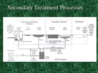
Secondary Treatment Configurations. SOP Pretreatment Workshop August 2011.

E N D
Secondary Treatment Configurations SOP Pretreatment Workshop August 2011
NDWRCDP DisclaimerThis work was supported by the National Decentralized Water Resources Capacity Development Project (NDWRCDP) with funding provided by the U.S. Environmental Protection Agency through a Cooperative Agreement (EPA No. CR827881-01-0) with Washington University in St. Louis. These materials have not been reviewed by the U.S. Environmental Protection Agency. These materials have been reviewed by representatives of the NDWRCDP. The contents of these materials do not necessarily reflect the views and policies of the NDWRCDP, Washington University, or the U.S. Environmental Protection Agency, nor does the mention of trade names or commercial products constitute their endorsement or recommendation for use.
CIDWT/University Disclaimer These materials are the collective effort of individuals from academic, regulatory, and private sectors of the onsite/decentralized wastewater industry. These materials have been peer-reviewed and represent the current state of knowledge/science in this field. They were developed through a series of writing and review meetings with the goal of formulating a consensus on the materials presented. These materials do not necessarily reflect the views and policies of University of Arkansas, and/or the Consortium of Institutes for Decentralized Wastewater Treatment (CIDWT). The mention of trade names or commercial products does not constitute an endorsement or recommendation for use from these individuals or entities, nor does it constitute criticism for similar ones not mentioned.
Pretreatment components • Section objectives • Describe various engineered systems that maintain high-rate aerobic digestion of organic compounds found in domestic wastewater • Provide an understanding of the typical issues associated with these components • Describe basic operation and maintenance procedures required to keep these systems functional
Basic aerobic treatment environments • Saturated • Suspended growth • Fixed/attached growth • Integrated fixed/activated sludge (IFAS) • Unsaturated • Media filters • Trickling filters
Saturated treatment • Suspended growth • Fixed/attached growth • Integrated fixed/activated sludge (IFAS)
Saturated aerobic units:Primary distinctions • Packaging • Flow of effluent • Aeration method • Biomass management
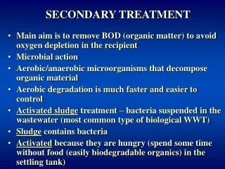
Suspended growth reactors • Activated sludge process • Biomass is thoroughly mixed with nutrients and biodegradable compounds • Organisms flocculate and form active mass of microbes - biological floc • Extended aeration to limit biomass wasting • Endogenous respiration
Suspended growth USEPA Manual, 1980
Sequencing Batch Reactor • Suspended growth treatment process • Utilize a single chamber for achieving aeration, clarification and anoxic conditions • Flow equalization chamber for dosing effluent into the treatment chamber
Fixed/attached growth reactors • Fixed-film process • Inert medium is submerged in the aeration chamber • Effluent circulated through media and attached microbes • Colloidal and dissolved organics compounds absorbed by biological film • Extended aeration to limit biomass wasting • Food brought to bugs
Membrane bioreactors Wikipedia
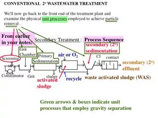
Flow schemes • Continuous inflow • Batch processes
Aeration • Air supply and delivery component • Distribution device • Venting device
Air supply delivery • Methods • Aspirator/Aerator • Compressor • Blower • Free Air
Aerator/Aspirator • Spinning shaft or impeller creates a vacuum (venturi) • Vacuum pulls air into the water
Compressor • Two distinct types of compressors • Rotary • Linear • Both types fitted with filters • Relative to blowers: • Greater pressure • Lower air flow Rotary Linear
Blowers • Fitted with inlet screens/filters • Relative to compressors: • Lower pressure • Greater air flow
Air distribution device • Introduces air into the water • Includes any supply line(s) • Various methods
Aspirator/aerator • Shaft piping delivers the air supply • Distribution relative to pressure
Diffused air distribution • Compressor or blower delivers air • Mode of distribution is manufacturer specific • Solid pipe • Perforated pipe • Holes • Slots • Porous material
Diffused air distribution Perforated Pipe
Diffused air distribution Porous ceramic diffuser
Diffused air distribution • Spargers • small interconnected passageways inside a ceramic matrix
Oxygen transfer into solution • Small diameter bubbles • More surface area per unit volume • Oxygen transfer takes place across interface between air and water
Point of injection • Usually near bottom of tank • more time for oxygen to go into solution • more hydrostatic pressure on bubble • more mixing of contents
“Free” air • Alternately rotates media through air space in top of unit and down into effluent in basin • Water accepts oxygen from air
Aeration and Mixing • Aeration system also encourages mixing • displacement of water as air is introduced causes turbulence
Air supply operation • Continuous • Timed
Venting • Air entering system • Air must exit somewhere • Unit • House vent • Biofilter
Biomass management • Returning sludge to a previous point in treatment system • Keeps the biological processes working • At some point, accumulated solids will have to be removed
Passive sludge return system Settled material automatically returns to the aeration chamber No moving parts Limited flexibility for including anoxic treatment process
Active sludge return system Pump on bottom of settling chamber Control panel with timer Timing of return Volume returned Location for returned material
Proprietary configurations • Modular units with complete configuration • Subcomponents installed in prefab tanks • Specific to proprietary products
Basic aerobic treatment environments • Saturated • Suspended growth • Fixed/attached growth • Integrated fixed/activated sludge (IFAS) • Unsaturated • Media filters • Trickling filters
Unsaturated treatment • Media filters • Trickling filters
Media filters • A container or lined excavation containing a specific media through which wastewater flows • Treatment occurs in unsaturated conditions • Designed to follow primary treatment
Flow regimes for media filters • Single pass • Recirculating
Typical configuration • 24 – 36 inches of media • Methods of distribution • Pressure distribution - most common • Spray nozzles • Driplines • Gravity
Typical configuration • Increasingly, timer-controlled dosing is being used • Usually lined to collect filtrate for external dispersal • May be configured to drain into rock pad beneath unit in certain soil/site conditions