Download
1 / 11
110 likes | 210 Views
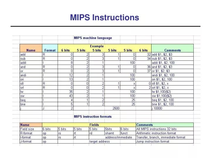
MIPS Instructions. Required ALU Functions. 7 functions:. ADD, SUB, AND, OR, XOR, SHL, SHR. Simple Implementation:. a i. b i. a i-1. a i+1. ADD. SUB. AND. OR. XOR. s. 3. Optimizations. Merge the ADD and SUB Assume 2’s complement Subtracting is adding a negative

E N D
Required ALU Functions 7 functions: ADD, SUB, AND, OR, XOR, SHL, SHR Simple Implementation: ai bi ai-1 ai+1 ADD SUB AND OR XOR s 3
Optimizations • Merge the ADD and SUB • Assume 2’s complement • Subtracting is adding a negative • Negate a number by inverting its bits and adding 1 b2 a1 b1 a0 b0 a2 s XOR XOR XOR FA FA FA
Break up the instructions into steps, each step takes a cycle balance the amount of work to be done restrict each cycle to use only one major functional unit At the end of a cycle store values for use in later cycles (easiest thing to do) introduce additional “internal” registers Multicycle Approach
Instruction Fetch Instruction Decode and Register Fetch Execution, Memory Address Computation, or Branch Completion Memory Access or R-type instruction completion Write-back step INSTRUCTIONS TAKE FROM 3 - 5 CYCLES! Five Execution Steps
Use PC to get instruction and put it in the Instruction Register. Increment the PC by 4 and put the result back in the PC. Can be described succinctly using RTL "Register-Transfer Language" IR <= Memory[PC]; PC <= PC + 4;Can we figure out the values of the control signals?What is the advantage of updating the PC now? Step 1: Instruction Fetch
Read registers rs and rt in case we need them Compute the branch address in case the instruction is a branch RTL: A <= Reg[IR[25:21]]; B <= Reg[IR[20:16]]; ALUOut <= PC + (sign-extend(IR[15:0]) << 2); We aren't setting any control lines based on the instruction type (we are busy "decoding" it in our control logic) Step 2: Instruction Decode
ALU is performing one of three functions, based on instruction type Memory Reference: ALUOut <= A + sign-extend(IR[15:0]); R-type: ALUOut <= A op B; Branch: if (A==B) PC <= ALUOut; Step 3 (instruction dependent)
Loads and stores access memory MDR <= Memory[ALUOut]; or Memory[ALUOut] <= B; R-type instructions finish Reg[IR[15:11]] <= ALUOut;The write actually takes place at the end of the cycle on the edge Step 4 (R-type or memory-access)
Reg[IR[20:16]] <= MDR; Which instruction needs this? Write-back step