Download
1 / 20
220 likes | 425 Views
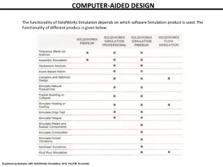
Explore CAQC benefits in quality enhancement, productivity, and waste reduction; integrate CIM systems for automated inspection and testing.

E N D
COMPUTER AIDED QUALITY CONTROL AND HANDLING SYSTEMS By Dr.J.Umamaheswari Department of mathematics St.Joseph’s College Trichy-2
INTRODUCTION The quality control (QC) function has traditionally been performed using manual inspection methods and statistical sampling procedures. INSPECTION AND TESTING Inspection is normally used to examine whether a product conforms to the design standards specified for it. For a mechanical component, this would be probably concerned with the dimensions, surface texture and tolerances specified for the part. Non-conforming goods result in scrap, rework, and the loss of customer goodwill. Various categories of tests used for final product evaluation: • Functional tests under normal or simulated operating conditions • • Fatigue or wear tests to determine the product’s life function until failure • • Overload tests to determine the level of safety factor built into the product • • Environmental testing to determine how well the product will perform under different environments (e.g. humidity, temperature, vibration).
OBJECTIVES OF CAQC Improve product quality ii. Increase productivity in the inspection process iii. Increase productivity iv. Reduce lead-time v. Reduce wastage due to scrap/rework ROLE OF COMPUTER IN QC Computer-aided inspection (CAI) and computer aided testing (CAT) are the two major segments of computer-aided quality control. Whereas these activities have been traditionally performed manually (with the help of gauges, measuring devices and testing apparatus),CAI and CAT are performed automatically using computer and sensor technology. To day, CAI and CAT can be well integrated into the overall CIM system.
The following list summarizes the important benefits of CAQC With Computer aided inspection and computer aided testing inspection and testing will typically be done on a 100% basis rather by the sampling procedures normally used in traditional QC. This eliminates any problem in assembly later and therefore is important in CIM. Inspection is integrated into the manufacturing process. This will help to reduce the lead-time to complete the parts. The use of non-contact sensors is recommended for computer aided inspection and CIM. With contact inspection devices, the part must be stopped and often repositioned to allow the inspection device to be applied properly. These activities take time. With non-contact sensing devices the parts can be inspected while in operation. The inspection can thus be completed in a fraction of a second. Sensor technology will not be the only manifestation of automation in CAQC. Intelligent robots fitted with computer vision and other sensors, as an integral part of completely automated test cells is also a feature of CIM. An important feature of QC in a CIM environment is that the CAD/CAM database will be used to develop inspection plan.
Inspection methods: 1. contact method 2. non contact method Contact method: In contact inspection, physical contact is made between the object to be inspected, and the measurement device. Typically contact is achieved using a mechanical probe or other device that touches the item, and allows the inspection procedure to occur. By its nature, contact inspection is concerned with some physical dimension of the part, and so contact methods are widely used in manufacturing and production industries to assess metal parts, and for electrical circuit testing. Conventional instruments Coordinate measuring machine Stylus measuring system
Convention measuring instruments: • scale • gauge bars • slip gauges • Vernier calipers • screw gauge 2. COORDINATE MEASURING MACHINE: The coordinate measuring machine (CMM) is the most prominent example of the equipment used for contact inspection of parts. When used for CIM these machines are controlled by CNC. A typical three-dimensional measuring machine consists of a table, which holds the part in a fixed, position, and movable head, which holds a sensing,probe. The probe can be moved in three directions corresponding to the X, Y and Z Coordinates. For manual operation, the control unit is provided with joysticks, or other devices which drive X, Y and Z servo motors (AC/DC). Typical accuracies of these machines are in the neighborhood of + 0.004 mm with are solution of 0.001 mm. The measuring accuracy of a typical CMM is quoted 2.6 +L/300 micrometers, where L is the measured length in mm
CMM consists of four main elements: 1. Main Structure: The machine incorporates the basic concept of three coordinate axes so that precise movement in x, y, and z directions is possible. Each axis is fitted with a linear measurement transducer. The transducers sense the direction of movement and gives digital display. Accordingly, there may be four types of arrangement: (a) Cantilever: The cantilever construction combines easy access and relatively small floor space requirements. It is typically limited to small and medium sized machines. Parts larger than the machine table can be inserted into the open side without inhibiting full machine travel.
Cantilever type Bridge Type (b) Bridge Type: The bridge arrangement over the table carries the quill (z-axis) along the x-axis and is sometimes referred to as a travelling bridge. It is claimed that the bridge construction provides better accuracy, although it may be offset by difficulty in making two members track in perfect alignment. This is by far the most popular CMM construction.
(c) Column Type: The column type machine is commonly referred to as a universal measuring machine rather than a CMM. These machines are usually considered gage room instruments rather than production floor machine. The constructional difference in column type with the cantilever type is with x and y-axes movements.
(d) Gantry: In a gantry type arrangement, arms are held by two fixed supports. Other two arms are capable of sliding over the supports. Movements of the x, y and z-axes. The gantry type construction is particularly suited for very large components and allows the operator to remain close to the area of inspection
(e) Horizontal: The open structure of this arrangement provides optimum accessibility for large objects such as dies, models, and car bodies. Some horizontal arm machines are referred to as layout machines. There are some horizontal machines where the probe arm can rotate like a spindle to perform tramming operations. Tramming refers to accurate mechanical adjustment of instrument or machine with the help of tram.
Stylus instrument: Stylus – type instruments are commercially available to measure surface roughness. These electronic device have a cone shaped diamond stylus with point radius of about 0.005mm and a 90° tip angle that is traversed across the test surface at a constant slow speed. As the stylus head moves horizontally, it also moves vertically to follow the surface deviations. The vertical movements are converted in to an electronic signal that represents the topography of the surface along the path taken by the stylus. This can be displayed as either 1. a profile of the surface or 2. an average roughness value.
Non contact inspection technologies: Noncontact inspection methods utilize a sensor located at a certain distance from the object to measure or gage the desired features. The noncontact inspection technologies can be classified into two categories: 1. optical 2. Non optical Optical inspection technologies use light to accomplish the measurement or gaging cycle. Non optical inspection technologies utilize energy forms other than light to perform the inspection. These other energies include various electrical fields, radiation and ultrasonic's. The main advantages of non-contact inspection are: It eliminates the need to reposition the workpiece. ii. Non-contact inspection is faster than contact inspection. iii. There is no mechanical wear encountered in the contact inspection probe. iv. The possibility of damage to the surface of a part due to measuring pressure is eliminated.
Machine Vision: Machine vision is the creation of an image and the collection of data derived from the image, and the subsequent processing and interpretation of the data by a computer from some useful application. Machine vision is also known as computer vision, and its principal application is in industrial inspection. Machine vision exists in two-dimensional (2D) and three-dimensional (3D) formats, with 2D being most common in industrial applications. Examples of its usage include dimensional measuring and gauging, verifying the presence of components, and checking for features on a flat (or semi-flat) surface. 3D machine vision is used in applications where a 3D analysis of the scene is required. Here we focus on the simpler 2D machine vision system. The operation machine vision system can be dived into the following three functions: 1. image acquisition and digitization. 2. image processing and analysis and 3. interpretation.
Image Acquisition and Digitization: Image acquisition and digitization is typically performed by deploying a video camera to capture the image, and the use of a digitizing system to store the image data for subsequent analysis. The camera is focused upon the surface of the item of interest, and an image consisting of discrete pixel elements is captured in the viewing area; each pixel has a value proportional to the light intensity of that portion of the scene. The intensity value of each pixel is converted into its equivalent digital value by an analogue-to-digital converter (a) scene presentation; (b) 12 x 12 matrix super-imposed; and (c) creation of pixelated scene and assignment of intensity values, in black or white
Image Processing and Analysis: A number of techniques have been developed so that data produced during the first phase of machine vision may be processed and analyzed. These general techniques are called segmentation (a technique intended to define and separate regions of interest within the image), and feature extraction (which follows on from various segmentation processes). Image processing and analysis techniques
Interpretation: The extracted features of the image are guide from which interpretation of the image emerges; that is, interpretation is concerned with recognizing the object (object recognition), and/or recognizing the major features of the object (pattern recognition). Predefined models or standard values are used to identify the object in the image. Two commonly-used interpretation techniques are. BULLETLIST Template matching a method whereby the features of the image are compared against corresponding features of a model or template stored in the computer memory . Feature weighting—a technique in which several features are combined into a single measure by assigning a weight to each feature according to its relative importance in identifying the object, and where the resultant score is compared against an ideal object score stored in computer memory, to achieve proper identification ENDLIST