Download
1 / 22
220 likes | 239 Views
Explore a comprehensive collection of robotics modules like servo motors, proximity sensors, and infrared detectors for building intelligent robots. Includes detailed circuit layouts and operation guides. Ideal for hobbyists and students.

E N D
Figure 12.2 Left: Radio Control Servo Motor and Right: Servo with Case and Gears Removed.
Figure 12.3 Line Tracker Module – 3 LEDs and Phototransistors are mounted on bottom of board
Figure 12.4 IR Proximity Sensor Module – Two IR LEDs on sides and one IR sensor in middle.
Figure 12.6 Circuit layout of one LED and the receiver module on the infrared detector.
Figure 12.7 Polaroid Sonar Module – Left: Sonar Transducer and Right: Controller Board.
Figure 12.11 UP1-bot Plexiglas Base with wheel slots and drill hole locations.
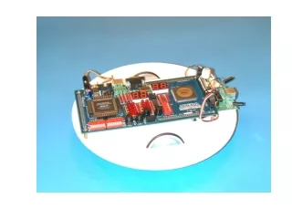
Figure 12.12 Bottom view of UP1-bot base showing battery, servos and cabling.
Figure 12.13 Top View of UP1-bot Base with Compass and IR Proximity Sensor Modules.
Figure 12.14 UP 1 Controlled R/C Car with IR Distance Sensors.
Figure 12.15 Robot Control IP Core with Pulsed Speed & Steering Control
Figure 12.16 Affect of Duty Cycle on Turning Angle and Speed
Figure 12.17 Interfacing to the R/C Car’s Internal Control Signals at the Demodulator IC.
Figure 12.18 Photo Showing Control Modications to R/C Car Control Board.