Download
1 / 51
510 likes | 664 Views
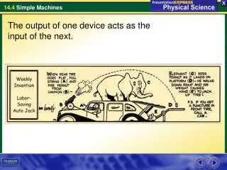
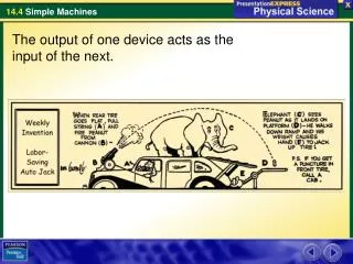
The output of one device acts as the input of the next. What are the six types of simple machines?. The six types of simple machines are the lever, the wheel and axle, the inclined plane, the wedge, the screw, and the pulley.

E N D
What are the six types of simple machines? The six types of simple machines are the lever, the wheel and axle, the inclined plane, the wedge, the screw, and the pulley.
What determines the mechanical advantage of the six types of simple machines? To calculate the ideal mechanical advantage of any lever, divide the input arm by the output arm. Levers
Levers A lever is a rigid bar that is free to move around a fixed point. The fixed point the bar rotates around is the fulcrum.
Levers The input arm of a lever is the distance between the input force and the fulcrum. The output arm is the distance between the output force and the fulcrum. Levers are classified into three categories based on the locations of the input force, the output force, and the fulcrum.
Levers First-Class Levers The fulcrum of a first-class lever is always located between the input force and the output force. Depending on the fulcrum position, the mechanical advantage can be greater than 1, equal to 1, or less than 1.
Levers The screwdriver is being used as a first-class lever with a mechanical advantage greater than 1. (Diagram is not drawn to scale.)
Levers Second-Class Levers • In a second-class lever, the output force is located between the input force and the fulcrum. • The input distance is larger than the output distance. • The mechanical advantage of a second-class lever is always greater than 1.
Levers The wheelbarrow has its output force located between the input force and the fulcrum. (Diagram is not drawn to scale.)
Levers Third-Class Levers • The input force of a third-class lever is located between the fulcrum and the output force. • The output distance over which the third-class lever exerts its force is larger than the input distance. • The mechanical advantage of a third-class lever is always less than 1.
Levers The output distance of the broom is greater than the input distance the hands move through. (Diagram is not drawn to scale.)
To calculate the ideal mechanical advantage of the wheel and axle, divide the radius (or diameter) where the input force is exerted by the radius (or diameter) where the output force is exerted. Wheel and Axle
Wheel and Axle A wheel and axle is a simple machine that consists of two disks or cylinders, each one with a different radius. The outer disk is the wheel and the inner cylinder is the axle. The wheel and the axle rotate together as a unit.
Wheel and Axle The input force can be exerted on the wheel or the axle. • If the force is applied to the wheel, the input distance is larger than the output distance. The mechanical advantage is greater than 1. • If the force is applied to the axle, the output distance is larger than the input distance. The mechanical advantage is less than 1.
Wheel and Axle A wheel and axle is a type of simple machine consisting of two disks or cylinders with different radii. Output Output Input Input Screwdriver shaft Steering shaft Screwdriver handle Steering wheel
The ideal mechanical advantage of an inclined plane is the distance along the inclined plane divided by its change in height. Inclined Planes
Inclined Planes An inclined plane is a slanted surface along which a force moves an object to a different elevation. • The distance traveled is the input distance. • The change in height of the ramp is its output distance. • The mechanical advantage of an inclined plane is greater than 1.
Inclined Planes This long and winding road acts like an inclined plane.
A thin wedge of a given length has a greater ideal mechanical advantage than a thick wedge of the same length. Screws with threads that are closer together have a greater ideal mechanical advantage. Wedges and Screws
Wedges and Screws Wedges A wedge is a V-shaped object whose sides are two inclined planes sloped toward each other. A wedge has a mechanical advantage greater than 1.
Wedges and Screws The wedge consists of two inclined planes that slope toward each other. The inclined planes force the wood fibers apart as the wedge is driven into the log. Input force
Wedges and Screws Screws A screw is an inclined plane wrapped around a cylinder. For two screws of the same length, the one whose threads are closer together moves forward less for each turn of the screw. A screw has a mechanical advantage greater than 1.
Wedges and Screws A screw is a simple machine made up of an inclined plane wrapped around a cylinder.
The ideal mechanical advantage of a pulley or pulley system is equal to the number of rope sections supporting the load being lifted. Pulleys
Pulleys A pulley is a simple machine that consists of a rope that fits into a groove in a wheel. • Pulleys produce an output force that is different in size, direction, or both, from that of the input force. • The mechanical advantage of a pulley can be equal to or greater than 1.
Pulleys A pulley moves a large fabricated part through a factory.
Pulleys Fixed Pulleys A fixed pulley is a wheel attached in a fixed location. The direction of the exerted force is changed by a fixed pulley, but the size of the force is not. The ideal mechanical advantage of a fixed pulley is always 1.
Pulleys Fixed Pulley A fixed pulley changes only the direction of the input force. 4 N 4 N 4 N
Pulleys Movable Pulley A movable pulley is attached to the object being moved rather than to a fixed location. • Both sections of the rope pull up with the same force. • The movable pulley has a mechanical advantage of 2.
Pulleys Movable Pulley 2 N 2 N Movable pulleys change both the direction and the size of the input force. 4 N
Pulleys Pulley System A large mechanical advantage can be achieved by combining fixed and movable pulleys into a pulley system. • The mechanical advantage depends on how the pulleys are arranged. • The ideal mechanical advantage of a pulley system is equal to the number of rope sections supporting the load being lifted.
Pulleys Pulley System Pulley systems are made up of both fixed and movable pulleys. 1 N 1 N 1 N 1 N 1 N 4 N
Pulley System Performance A shipyard has many different pulleys and pulley systems in use. The pulleys are used to move large, heavy, fabricated ship sections through the manufacturing process. During an annual safety and performance inspection of three of the company’s systems, a facility engineer collected the data shown in the graph. The data give the measured output forces for a range of given input forces.
Exploring Boiling Points of Chlorocarbons • Using GraphsWhat system requires the smallest input force to lift a 2500-N load? Answer:
Exploring Boiling Points of Chlorocarbons • Using GraphsWhat system requires the smallest input force to lift a 2500-N load? Answer: System C
Exploring Boiling Points of Chlorocarbons • CalculatingDetermine the actual mechanical advantage for each of the systems for a 2000-N input force. Answer:
Exploring Boiling Points of Chlorocarbons • CalculatingDetermine the actual mechanical advantage for each of the systems for a 2000-N input force. Answer: AMA = Output force/Input force A: AMA = 1; B: AMA = 2; C: AMA = 8
Exploring Boiling Points of Chlorocarbons • Applying ConceptsWhich of the three systems shown in the graph consists of a single fixed pulley? Explain how you know. Answer:
Exploring Boiling Points of Chlorocarbons • Applying ConceptsWhich of the three systems shown in the graph consists of a single fixed pulley? Explain how you know. Answer: System A could be a fixed pulley because it has a mechanical advantage of 1.
Exploring Boiling Points of Chlorocarbons • InferringDescribe what happens to system B’s output force as the input force increases above 4000 N. How does this affect the mechanical advantage of the system at higher loads? Offer a possible cause for the performance shown in the graph.
Exploring Boiling Points of Chlorocarbons • InferringDescribe what happens to system B’s output force as the input force increases above 4000 N. How does this affect the mechanical advantage of the system at higher loads? Offer a possible cause for the performance shown in the graph. Answer: The output force begins to decrease relative to the required input force. At higher loads the mechanical advantage is decreased. Increased friction at higher loads could be a cause.
Exploring Boiling Points of Chlorocarbons • Applying ConceptsUsing the mechanical advantage value from Question 2, determine the output force of system A for an input force of 8000 N. Answer:
Exploring Boiling Points of Chlorocarbons • Applying ConceptsUsing the mechanical advantage value from Question 2, determine the output force of system A for an input force of 8000 N. Answer: 8000 N
Compound Machines • A compound machine is a combination of two or more simple machines that operate together. Most of the machines you use are compound machines. • The edges of a pair of scissors are sharpened like wedges. The blades and the handles together function as levers. • Cars, washing machines, and clocks are combinations of hundreds or thousands of simple machines.
Compound Machines This watch consists of a series of machines. The output of one machine acts as the driving input for the next machine in the series.
Assessment Questions • A bar that is rotating about a fixed point is called a • fulcrum. • lever. • wedge. • compound machine.
Assessment Questions • A bar that is rotating about a fixed point is called a • fulcrum. • lever. • wedge. • compound machine.ANS: B
Assessment Questions • A 3-meter-long ramp is used to lift a piano to a moving truck, which is 1 meter off the ground. What is the ideal mechanical advantage of the ramp? • 1 • 2 • 3 • 33
Assessment Questions • A 3-meter-long ramp is used to lift a piano to a moving truck, which is 1 meter off the ground. What is the ideal mechanical advantage of the ramp? • 1 • 2 • 3 • 33 ANS: C
Assessment Questions • A machine, such as a bicycle, that combines many simple machines is known as a complex machine.TrueFalse