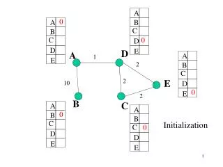
Installation and Initialization
NS1000. Installation and Initialization. Introduction. This material refers to the KX-NS1000 PBX system, and details the basic steps necessary to install and initialize the unit. The Module comprises of the following sections; NS1000 – Installation NS1000 – System Initialization

Installation and Initialization
E N D
Presentation Transcript
NS1000 Installation and Initialization
Introduction • This material refers to the KX-NS1000 PBX system, and details the basic steps necessary to install and initialize the unit. • The Module comprises of the following sections; • NS1000 – Installation • NS1000 – System Initialization • From following this course element, participants will be gain an understanding of how to install and initialize the NS1000 ready for first use. • Further information about feature implementation and specifications, may be found in the associated Installation Manual, Feature Guide and User Manual.
Contents • Chapter 1 Installation • 1.1 Unpacking • 1.2 Component Location • 1.3 Option Installation • 1.4 Rack Mounting • 1.5 Desk Mounting • 1.6 Wall Mounting • 1.7 Earth / Surge Protector connection • 1.8 Connecting Power • 1.9 External Connections • Chapter 2 System Initialization • 2.1 System Initialization • 2.2 Web Console Preparation • 2.3 Web Console Connection • 2.4 1st Login • 2.5 Easy Setup • Chapter 3 Slave Initial Configuration • 3.1 Slave Initial Configuration • 3.2 Slave Registration • Chapter 4 System Outline • 4.1 UPS Connection and setting
Chapter 1 Installation
NOTE • IMPORTANT: • Before installing the NS1000 system, refer to the Installation Manual. The Installation Manual contains specific information regarding the safe installation of the unit and also details specific installation and wiring precautions. • The information contained in this presentation is intended to supplement the NS1000 Installation Manual by providing an overview of the installation and initialization process and in no way replaces the published Installation Manual. • Where any information contained herein appears unclear or incomplete, the information contained in the published NS1000 Installation Manual shall take precedence.
1.1 Unpacking (1) • Unpacking • Remove the NS1000 from the box and check that the following items are present;
1.2 Component Location (1) • Component location (External) • The main ports, jacks and LEDs etc are shown below; Front Side LED indicators MOH/EPG ports DPH Port (Option) Legacy Slot (Option) System mode SW USB port IP ports Back Side AC SW GROUND Serial port FAN AC cord clamp AC IN
1.2 Component Location (2) • Component location (Internal) • The expansion/option slots are shown below; Slot(Doorphone) Slot(FAX Server) Slot(Trunk/SLT) Slot(Trunk/SLT) Slot(DSP 2) Slot(DSP 1)
1.3 Option Installation (1) Option Installation • Optional cards can be installed when the top cover is removed. • Option Cards are not “Hot-Swap” • Power must be removed from the unit before optional cards are installed 1. Ensure the Power Switch is ‘OFF’ 2. Remove 3 screws from the rear of the top cover. NB: Where possible, Option cards should be installed before installing and powering-on the unit for the first time. When this is not possible, the system must first be ‘SHUTDOWN’ using the Web Maintenance Console. Removing the power without shutting down the unit may damage the systems file-structure and render the system inoperable.
1.3 Option Installation (2) • Option Installation • The required options can now be installed. 3. Remove the cover 4. Install the required options 5. Replace the top cover and screws. CAUTION: When installing or removing option cards, do not put pressure on the main board. Damage to the option and main board may result.
1.4 Rack Mounting Rack Mounting the NS1000 The NS1000 can be rack-mounted using the supplied brackets and screws. • Mount the brackets onto the NS1000. • Bolt the NS1000 into the rack using the hardware supplied by the rack manufacturer. Size = 2U Dimensions: 430mm×88mm×340mm Weight : Under 4.5kg (Fully Mounted) NB: Ensure that there is sufficient ventilation around the system and that the rack temperature limit is not exceeded. (Refer to the Installation manual for further details)
1.5 Desk Mounting Desk Mounting the NS1000 The NS1000 can be installed on a flat surface. • The unit MUST be placed flat on it’s base (Not on it’s back, sides or upside-down etc) • The units FAN opening MUST be clear • A 10cm gap around the sides and 20cm over the top of the unit MUST be maintained. • DO NOT place flammable (wood etc) objects behind the unit (Refer to the Installation Manual for more details)
1.6 Wall Mounting • Wall Mounting the NS1000 • The NS1000 can be installed onto a suitable wall using the optional Wall Mounting kit. • (Refer to the Installation Manual for further details) 1. Install the screws (with suitable wall anchors etc) 2. Mount the unit to the wall (using the Wall Mounting Kit) NB: The unit must be installed with the arrows on the Wall Mounting brackets pointing “UP”. In any other orientation, the unit will not be secured correctly to the wall and may fall.
1.7 Earth / Surge Protector connection • Frame Ground (Earth) and Surge Protection • (Refer to the Installation Manual!) Frame Ground Surge Protection • WARNING • Proper connection to earth is very important to reduce the risk to the user of electrocution or to protect the PBX from the effects of external noise or lightning strike. • The earth wire of the AC cable has an effect against external noise and lightning strikes, but it may not be enough to protect the PBX and to ensure electromagnetic compatibility. A permanent connection between earth and the earth terminal of the PBX must be made. • To protect the system from electrical surges, it is strongly recommend to connect the system to a surge protector that meets the following specifications: • Surge arrestor type: 3-electrode arrestor • DC spark-over voltage: 230 V • Maximum peak current: at least 10 kA • Many countries/areas have regulations requiring surge protection. • Be sure to comply with all applicable laws, regulations, and guidelines.
1.8 Connecting Power • Connecting the AC Cord • Using the AC Cord supplied with the unit, connect it to the PBX and secure with the supplied AC Cord Clip. Connect the other end of the AC Cord to the UPS System. AC Cord Clip UPS System: A UPS should be connected to the PBX to provide temporary in the event of a power failure. When using the recommended UPS (APC RS Series with USB interface), the PBX can shutdown automatically by sending a warning signal to the PBX through the USB port. By shutting down correctly, data loss or serious damage to the PBX caused by a sudden power cut can be prevented. When power is restored, turn off the PBX using the power switch first, and then turn the PBX back on before starting the PBX.
1.9 External connections • Connecting Peripherals and Options • Once the NS1000 has been mounted, various peripherals and options can be connected. • (Refer to the Installation Manual for further details)
Chapter 2 System Initialisation
2.1 System Initialisation BATT ALARM MASTER STATUS After installing the option cards, initialize the system (factory default settings) • Ensure the power switch is OFF. • Slide the System Mode Switch to the “SYSTEM INITIALIZE” position. • Turn the power switch ON. (STATUS and MASTER LED will flash AMBER), the STATUS LED will then flash GREEN. • Slide the System Mode Switch back to the “NORMAL” position. (When the STATUS LED is flashing.) System Mode Switch STATUS = RED (No DHCP) STATUS = GREEN (DHCP) MASTER = Flashing AMBER (Master/Slave not assigned) Indicators 5. When successfully executed, the STATUS indicator will stop flashing and stay lit. (RED or GREEN) Refer to Appendix for LED Sequence Detail.
2.2 Web Console Preparation • Below are the system requirements necessary for Web Connection to the NS1000 • PC Requirements Supported Browsers Browser Settings • Enable the following functions in the browser's settings: • Cookies • JavaScript • The ability to download files • The display of animations • The display of images Windows Internet Explorer 7 or 8 Mozilla Firefox 4 Apple Safari 5
2.3 Web Console Connection • When the system has been initialized, the Setup Wizard can be run via the Web Maintenance Console (Web-MC). • Connecting a PC to the NS1000 via the Web-MC DHCP Client DHCP Server • Set your PC as a DHCP Client (Automatically Obtain IP Address.) • Connect your PC to the MNT Port of the NS1000 (Default IP Address 223.0.0.1) • Open you Browser and enter the URL http://223.0.0.1/WebMC • The Web Maintenance Console login screen will then be displayed in your browser.
2.4 First Login (Factory Default Setting) • When connecting to the system for the first time, the Easy Setup Wizard will launch. 1st Login(The PBX is in the factory default state) Default Settings: Username: INSTALLER Password: 1234 2. Click Install 1. Select the Web-MC Language Note: The Web session expires after 10min (default). The Easy Setup Wizard must be completed within this time, or the settings will be lost.
2.5 Easy Setup (1) • Location Setting • 1. Set the unit status (Master/Slave), Suffix and Area Set the unit as Master or Slave. Set the unit Suffix Code (UK, NE, CE, GR etc) and your required country. The Suffix Code can be found on the units Nameplate and box Click ‘Next’ to continue. • If the Unit is to be configured as a Slave unit of a One-Look System on a Remote Site (Different Network than the Master), then set the PBX Type as ‘Slave’ and enter the Master PBX IP Address in the Location Setting. (Master units in a One-Look system or Stand-Alone units must be configured as a ‘Master’. • It is important to select the correct Suffix/Country settings so that the correct default tones, emergency dial and other country specific data are set automatically.
2.5 Easy Setup (2) • PBX Setting • 2. Give the system an appropriate name and set the Time Zone Use a name which easily identifies the unit. Select the Time Zone. The Local date and time are obtained automatically from your PC. Check that the PC date/time is correct. Click ‘Next’ to continue.
2.5 Easy Setup (3) • LAN Setting • 3. Enter the required LAN Settings By default, the PBX uses a static IP Address (Recommended) By default, no DNS server addresses are set. Configure them as required. By default, the DSP Cards use DHCP to obtain an IP-Address, however static addresses can also be assigned. Click ‘Next’ to continue. Note: If you are Not using DHCP then you Must assign a DSP IP Address Manually.
2.5 Easy Setup (4) • LAN Setting • 4. Enter the IP Terminal Registration Mode setting and select if ‘One-Look’ Trial should start. There are three terminal registration Modes; Manual: Suitable for all supported IP Terminals and network configurations. Registration information is set manually in the Terminal and PBX. (This is the recommended setting when a range of IP/SIP Terminals will be used with the system.) Full Automatic: Suitable for UT/NT Terminals connected to the same network as the PBX. All settings, including Extension Number are registered automatically. NB: DHCP Server Required Extension Number Input: Suitable for NT Terminals connected to the same network as the PBX. All network and registration settings are registered automatically. The Extension number is configured manually via the Terminal. NB: DHCP Server Required If ACTIVE is selected, then the 60-day One-Look Trial will start. If NON-ACTIVE is selected, it is possible to Activate the Trial at a later date. Click ‘Next’ to continue. • Note: • Non-UT Series SIP Terminals must be registered manually. • By default, the UT-Series SIP Extension password is automatically set to ‘1234’
2.5 Easy Setup (5) • SNTP (Simple Network Time Protocol) / Daylight Saving Setting • 5. The source used for automatic time adjustment and the Daylight Saving mode is set here. • This is useful to keep the time displayed on the terminals and SMDR records etc accurate. Automatic Time Adjustment can be made using ISDN/Analogue Trunks (ISDN/FSK) or via a suitable SNTP server. For countries using ‘Daylight Saving’ - automatic adjustment can be set here. Click ‘Next’ to continue.
2.5 Easy Setup (6) • Maintenance / Remote Management Settings • 6. The Installer Password can be changed (Strongly Recommended) and SNMP (Simple Network Management Protocol) can be configured here. Be sure to change the default Installer password up installation. Use a strong password. Check the required SNMP settings with the Network Administrator and enter as required to enable Remote Management. Click ‘Finish’ to complete Easy Setup.
2.5 Easy Setup (7) • If the systems LAN settings were changed during Easy Setup, you will be prompted to restart the PBX so that the changes can take effect. Be sure to login with the new password etc 2nd Login(Easy Setup has been completed) Login with the new password. Detailed system configuration can now be made.
2.5 Easy Setup (8) • By Default, the WebMC portal will only remain active (without activity) for 10 minutes. • This may not be sufficient time for all operations / configurations etc. • To change the WebMC Portal settings, change the time here after 2nd login :- Settings To change the WebMC Auto Logout timer – change this setting. Network Service 5. HTTP
Chapter 3 Slave Initial Configuration
3.1 Slave Initial Configuration Location Setting • Set the unit status as Slave. • Enter the IP Address of the Master System. Set the unit as Slave. Enter the IP Address of the Master Unit. Default IP Address: 192.168.0.101 Click ‘Next’ to continue.
3.1 Slave Initial Configuration • LAN Setting • 3. Enter the required LAN Settings. Change the IP Address to a different number within the same range Change the IP Address to a different number within the same range Click ‘Next’ to continue. Note: If you are Not using DHCP then you Must assign a DSP IP Address Manually.
3.1 Slave Initial Configuration LAN Setting Note: Once the LAN settings has changed, the system will need to reboot. The bellow pop-up will be displayed. Click OK to reboot system.
3.1 Slave Initial Configuration Registration Setting 4. Enter the IP Terminal Registration Mode as Manual. Full automatic can be used but is not covered in this document. Manual entry reduces the number of Empty Extension numbers in CA. Activate the 60-day One-Look Trial if required. Click ‘Next’ to continue. • Note: • Non-UT Series SIP Terminals must be registered manually. • By default, the UT-Series SIP Extension password is automatically set to ‘1234’
3.1 Slave Initial Configuration SNTP (Simple Network Time Protocol) / Daylight Saving Setting 5. The source used for automatic time adjustment and the Daylight Saving mode is set here. This is useful to keep the time displayed on the terminals and SMDR records etc accurate. Automatic Time Adjustment can be made using ISDN/Analogue Trunks (ISDN/FSK) or via a suitable SNTP server. For countries using ‘Daylight Saving’ - automatic adjustment can be set here. Click ‘Next’ to continue.
3.1 Slave Initial Configuration • Maintenance / Remote Management Settings • 6. The Installer Password can be changed if required. Even if you want to keep as default (1234) you must re-enter it here before continuing. Even if you want to keep the default password you must re-enter it before continuing. Click ‘Finish’ to complete.
3.1 Slave Initial Configuration • If the systems LAN settings were changed during Easy Setup, you will be prompted to restart the PBX so that the changes can take effect. Be sure to login with the new password etc 2nd Login(Easy Setup has been completed) Login with the new password. Detailed system configuration can now be made.
3.2 Slave Registration • Once the both systems have been initially configured, the Slave system needs to be added to the Master system network. Log into the Master system. You will be presented with the bellow screen. Click on the Add Site Button. Add Site Follow the prompts to add the desired Slave site.
3.2 Slave Registration • Once the Slave system has been added to the network, the Slave system needs to be registered to the Master system. Log into the Master system. You will be presented with the bellow screen. Click on the List button. List View
3.2 Slave Registration • Click on the Registration button. From the popup, select the Slave system displayed in the list and click Next. Click on Registration Select Slave Unit Select move button Click Next
3.2 Slave Registration • Once the Slave is registered, it will show in the list view. Pressing the Home button will show the systems in the Tree view. This is displayed on the next slide.
3.2 Slave Registration • Once the Slave has been registered, it will show on the Home screen (In-Service).
Chapter 4 Ups connection
4.1 UPS Connection and setting (1) UPS (Uninterruptible Power Supply) Integration Description An uninterruptible power supply unit (UPS) is a device that supplies power for several minutes to a connected device when a power failure occurs. If the PBX is connected to a compatible UPS via USB when a power failure occurs, the PBX can determine how much power remains in the UPS and shut down when the remaining power drops below a specified amount to prevent data loss or corruption. The following features are also available: • Specify the remaining battery level at which to shut down the PBX. • Receive e-mail notifications of changes to the status and availability of a UPS. Conditions • For details about UPS units that are compatible with the automatic shutdown feature of this PBX, consult your dealer. If an incompatible UPS is connected and the UPS runs out of power, the PBX will turn off without shutting down. • The power cord and USB cable must be connected to the same UPS. Connecting them to different UPSs can result in incorrect operation. IMPORTANT • When power is restored after a power outage, the PBX operates in the following manner: – If the PBX did not shut down, normal operation continues uninterrupted. – If the PBX shut down and power remains in the UPS, the PBX must be started again manually. (The power switch must be turned off and then on again.) – If the PBX shut down and no power remains in the UPS, the PBX starts automatically. (This is because the PBX's power switch is on.)
4.1 UPS Connection and setting (2) 1. Connect the UPS as described in the Installation manual 2. Set the NS1000 Shutdown threshold via the WebMC Maintenance -> Status -> Equipment Status -> 1. UPS UPS Status can be seen here Set the UPS Battery Level, that when reached, will cause the PBX to Shutdown NB: UPS Status alerts can also be sent via email.