L. Ratti
Monolithic and hybrid pixel sensors in vertically integrated CMOS technology for vertexing applications. L. Ratti. Università degli Studi di Pavia and INFN Pavia. OUTLINE. First test results from 3D DNW MAPS characterization 3D technology design features characterization results.

L. Ratti
E N D
Presentation Transcript
Monolithic and hybrid pixel sensors in vertically integrated CMOS technology for vertexing applications L. Ratti Università degli Studi di Pavia and INFN Pavia OUTLINE First test results from 3D DNW MAPS characterization • 3D technology • design features • characterization results University of Bergamo and INFN Pavia Luigi Gaioni, Massimo Manghisoni, Valerio Re, GianlucaTraversi University of Pavia and INFN Pavia AlessiaManazza, Stefano Zucca Design of 3D monolithic and hybrid pixels for the SuperBFactory
Vertex detectors in future HEP experiments Experiments at the future particle colliders (or upgrade of present colliders) will set severe requirements for silicon vertex trackers thin detectors small amount of support material and interconnection low material budget low mass cooling power dissipation high functional density vertical integration technologies high granularity small pixel pitch data sparsification large hit rate small distance from the interaction point digital-to-analog interference mixed-signal chips large background in DNW MAPS, efficiency loss due to N-wells CMOS, hardening by design radiation hardness
The 3D-IC collaboration Several groups from US and Europe have been involved in the first 3D MPW for HEP (pixel and strip readout chips for ATLAS, CMS, B-factory, ILC) and photon science applications (X-ray imaging) ~ 3.2 cm Single set of masks used for both tiers to save money identical wafers produced by Chartered (now Globalfoundries) and face-to-face bonded by Tezzaron backside metallization by Tezzaron ~ 2.5 cm
Tezzaron vertical integration (3D) technology TSV WB/BB pad In wafer-level, three-dimensional processes, multiple strata of planar devices are stacked and interconnected using through silicon vias(TSV) 3D processes rely upon the following enabling technologies Inter-tier bond pads Fabrication of electrically isolated connections through the silicon substrate (TSV formation) Substrate thinning (below 50um) Inter-layer alignment and mechanical/electrical bonding 1st wafer Tezzaron Semiconductor technology (via middle approach, vias are made between CMOS and BEOL) can be used to vertically integrate two 130 nm CMOS layers specifically processed by Globalfoundries 2nd wafer Fabrication took quite a long time due to a number accidents both at the foundry and at the vertical integration facilities – the first 3D wafers became available by beginning of last summer
From 2D to 3D DNW MAPS Deep N-well monolithic pixels A large DNW is used to collect the charge released in the substrate A classical readout channel for capacitive detectors is used for Q-V conversion gain decoupled from electrode capacitance NMOS devices of the analog section are built in the deep N-well Full CMOS for high performance analog and digital blocks charge collection inefficiency depending on the relative weight of NW with respect to DNW What can be gained from going 3D sensor and analog front-end can be integrated in a different layer from the digital blocks less PMOS in the sensor layer improved collection efficiency more room for both analog and digital power and signal routing Tier 1: collecting electrode and NMOS parts of the analog front-end (and a few PMOS) Tier 2: discriminator PMOS parts, digital front-end and peripheral digital readout electronics
0.95 ms 337 ns 0.2 s Digital readout x2820 intertrain interval bunch train interval 3D DNW MAPS for the ILC vertex tracker Bunch structure of the ILC beam 20 um pitch monolithic pixel Sparsification based on a token passing scheme Double hit storage and double 5-bit time stamp register • Chip operation tailored on the ILC beam structure • detection phase, corresponding to the bunch train interval • readout phase, corresponding to the intertrain interval
DNW MAPS test structures Small test structures single pixels with and w/o detector emulating capacitor shunting the readout channel input (analog only) 3x3 DNW MAPS matrices (analog only, for charge collection tests) 8x8 and 16x16 DNW MAPS matrices (analog and digital, for readout architecture test) ~ 5.2 mm ~ 6.3 mm 1st wafer metal + oxide +2nd wafer substrate
Analog front-end characterization Test of single channels and small matrices Peaking time of about 1 us, increasing with increasing input charge (as anticipated by simulations due to the non-linearity in the feedback network) DUT is located in the thick tier – signals and power supply are fed through TSVs and inter-tier bond pads Slew rate limitations on the rising edge in a number of samples
Analog front-end characterization ENC: 35 - 40 electrons (good agreement with simulations) Estimated DNW capacitance: ~250 fF (about 25% larger than in circuit simulation) Charge sensitivity: ~700 mV/fC (~12% less than the design value) Input dynamic range: ~2000 electrons (good agreement with simulations)
DNW sensor test Collected charge as a function of the laser beam position Obtained by retro-illumination with an infrared laser Response to a laser pulse Some problems in getting more quantitative data on collection efficiency and charge sharing – laser beam is likely to be scattered from the irregular back-surface of the dice (which was not back-lapped)
Digital readout Signals from an 8x8 matrix (detail of the first readout cells, fCK=20 MHz) TOKEN-IN (readout can start after the rising edge) READOUT-CK (clocks the serializer at the chip periphery) DATA-OUT (address and time-stamp, hit pixels read out serially) CELL-CK (one CELL-CK period is needed to read out a hit from one cell) Operation up to 50 MHz seems feasible
Digital readout Signals from an 8x8 matrix (complete readout cycle, fCK=20 MHz) TOKEN-IN Npixel x NbitxTck = = 64 x 24 x 50 ns = 76.8 us TOKEN-OUT (readout stops on the rising edge) DATA-OUT During the test, all the pixel cells were always found to report a single hit (unless the MASTER-RESET signal is kept active during readout or the kill mask is used)
Layer misalignment wire bond pad wire bond pad Redundant inter-tier connection makes the signal path to and from the wire bond pads more robust level triggered always set to 1 always set to 1 (unless killed or reset) Single inter-tier connections between circuits on the two tiers – while the single sections work, misalignment by a single inter-tier pad makes the overall circuit non operable edge triggered never set to 1
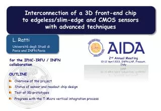
3D options for the SuperB SVT Layer0 Design of the SVT layer0 at SuperB has to comply with severe requirements large background, ~150 MHz/cm2 (including a x5 safety factor), small thickness, <1% X0 3D hybrid pixel detectors vertically integrated, mixed-signal circuit for a pixel detector in high resistivity silicon - fine pitch (50 μm) bump bonding (IZM, Munich) or more advanced technologies (direct bonding by Ziptronix, or u-bump bonding by T-Micro) – based on a 130 nm dual tier CMOS process - 128x32 element chip to be submitted in the next run Direct bonding (Ziptronix) or u-bump bonding (T-Micro) 3D DNW MAPS sensors deep N-well sensors were proposed to enable fast readout through pixel-level sparsification and time stamping - DNW sensor in an undepleted substrate, analog front-end for capacitive detectors, analog and digital blocks integrated in separate layers – based on a 130 nm dual tier CMOS process - a 128x96 pixel chip is being designed for the next run
3D front-end for hybrid pixels: the SuperPix1 chip polarity select TIER 1 TIER 2 shift-out shift-in C2 C1 THR DAC A(s) CF VGTHR 50 um pitch Polarity selection Power dissipation: 12 uW/pixel Threshold dispersion: 560/65 e-rms (before/after correction) Peaking time: 250 ns (slightly dependent on input charge) Digital section: in-pixel time-stamp, time-ordered triggered or data-push readout ENC=190 e-rms @CD=150 fF Charge sensitivity: 50 mV/fC
Analog front-end for the ApselVI 3D MAPS chip shift-out shift-in C2 C1 THR DAC A(s) CF VGTHR VREF 50 um pitch TIER 1 TIER 2 Power dissipation: 33 uW/pixel RC-CR shaping Peaking time: 320 ns Blocks for voltage drop (along power and ground lines) and temperature compensation ENC=38 e-rms @CD=290 fF Charge sensitivity: 875 mV/fC Threshold dispersion: 95/12 e-rms (before/after correction) Digital section: same as for the hybrid pixel front-end
Conclusion First tests on 3D deep N-well MAPS prototypes for vertexing applications have been performed analog section works fine – some linearity issues (slew rate limitations), thorough characterization of the charge collection properties still missing (tests with radioactive sources are needed) only part of the functionalities of the digital (single hit readout, reset, kill mask) section could be tested – no inter-tier interconnection between circuits likely due to misalignment analog section could be tested as a result of redundancy in inter-tier interconnection under wire bond pads – also TSVs do their job Planar wafers from the same run are being vertically integrated – new chips by beginning 2012 The design of new 3D DNW MAPS and of a 3D front-end chip for hybrid pixels is in progress – submission by end of March 2012
tki tki tki tki tki tki tki tki tki gX gX gX gX gX gX gX gX gX TS TS TS TS TS TS TS TS TS tko tko tko tko tko tko tko tko tko gY gY gY gY gY gY gY gY gY tki tki tki tki tki tki tki tki tki gX gX gX gX gX gX gX gX gX TS TS TS TS TS TS TS TS TS tko tko tko tko tko tko tko tko tko gY gY gY gY gY gY gY gY gY Token passing readout architecture (240x256 DNW MAPS matrix) ReadOutCLK DataOut MUX 8 5 gX=GetX gY=GetY TS=TimeStampOut tki=TokenIn tko=TokenOut X=1 TSBUF X=2 TSBUF X=256 TSBUF FirstTokenIn 8 Y=1 Y=2 Time stamp counter Y=240 LastTokenOut
Digital readout at 50 MHz Signals from an 8x8 matrix (detail of the first readout cells) TOKEN-IN (readout starts on the rising edge) READOUT-CK (clocks the serializer at the chip periphery) DATA-OUT (address and time-stamp, hit pixels read out serially) CELL-CK (one CELL-CK period is needed to read out a hit from one cell)
Digital readout at 50 MHz Signals from an 8x8 matrix (complete readout cycle) TOKEN-IN Npixel x NbitxTck = = 64 x 24 x 20 ns = 30.7 us TOKEN-OUT (readout stops on the rising edge) DATA-OUT
Channel response Slight nonlinearity due to the nonlinear shaper feedback network
Time ordered readout with in-pixel time stamp No macropixel Timestamp (TS) is broadcast to pixels; pixel latches the current TS when fired Matrix readout is timestamp-ordered A readout TS enters the pixel and a HIT-OR-OUT is generated for columns with hits associated to that TS TSComp. A column is read only if HIT-OR-OUT=1 DATA-OUT (1 bit) is generated for pixels in the active column with hits associated to that TS DATA-OUT HIT-OR-OUT More in pixel logic with 3D integration by F. Morsani, Pisa Readout can be data push and or triggered
Voltage drop compensation AVDDperipheral AVDDpixel Isib≈120 nA I=120 nA Itransc≈ 2.5 nA AGNDperipheral AGNDpixel M. Manghisoni, E. Quartieri et al.,“High Accuracy Injection Circuit for Pixel-Level Calibration of Readout Electronics”, presented at the 2010 IEEE Nuclear Science Symposium Conference, Knoxville, USA, October 30 - November 6 2010.
Effects on output waveform Voltage drop is simulated as a symmetrical voltage variation in the analog power (AVDD) and ground (AGND) lines AVDD=1.5 V-ΔVd, AGND=ΔVd w/o voltage drop compensation with voltage drop compensation